Lathe Features Overview
Introduction
Lathe Features can be thought of as simply as you would the features of the final product itself. For any feature of the part itself, work will have to be done to create it. Any work you choose to do on a feature will be an operation that you add. To create a feature, right-click on the Machine Setup and choose between Lathe End Face, Lathe Turning, Lathe Groove, Lathe Hole, Lathe Tap Hole, Lathe Thread, Lathe Cutoff, and Lathe Stock Handling. Once the feature is chosen and the Lathe Wizard is launched, you will be able to select any number of operations needed to complete the chosen feature.
When you create a lathe feature and finish the feature wizard, the feature is added to the Lathe Job in the CAM Tree. All of the information from the wizard can be viewed or modified using the feature in the CAM Tree. Each item of the feature contains a shortcut menu for you to access various functions and commands.
Turning Feature

 Feature Lathe Turning


 Geometry
 Default
Chain Start Point
Default
Chain Start Point

 Rough
Rough


 Operation
Stock
Operation
Stock
 Basic
Finish
Basic
Finish
Operation
Stock
 Pattern Repeat
Operation Stock
The Feature Shortcut Menus
You right-click each feature item in the tree to access a shortcut menu. The menus handle various software commands as explained next.
Feature Creation and Modification
The top level of the feature, which displays the feature name, is used to edit the feature, insert features, and set the feature status using the following commands.
Note: When you insert a feature, it is added below the current feature.
Feature Type
-
Edit - opens the Lathe Wizard dialog box for you to edit the feature.
-
Compute All Toolpath - computes the operations of all features contained in the Machine Setup.
-
Update All Geometries - Updates all geometry associated in the CAM Tree.
-
Insert Lathe End Face - opens the Lathe Wizard for you to create a Lathe Turning feature. This handles the facing off of the part with the available operations: Rough, and Basic Finish.
- Insert Lathe Turning - opens the Lathe Wizard for you to create a Lathe Turning feature. This handles ID and OD machining with the available operations: Rough, Basic Finish, and Pattern Repeat.
- Insert Lathe Groove - opens the Lathe Wizard for you to create a Lathe Groove feature. This handles ID and OD machining with the available operations: Groove Rough, Groove Basic Finish.
- Insert Lathe Holes - opens the Lathe Wizard for you to create a Lathe Hole feature. This handles drilling with the available operations: Center Drill, Drill, Chamfer, Bore, and Ream.
- Insert Lathe Tap Hole - opens the Lathe Wizard for you to create a Lathe Hole feature. This handles tapping with the available operations: Center Drill, Drill, Chamfer, Ream, Tap.
- Insert Lathe Thread - opens the Lathe Wizard for you to create a Lathe Thread feature. This handles threading with the available operation: Thread.
- Insert Lathe Cutoff - opens the Lathe Wizard for you to create a Lathe Cutoff feature. This handles part/stock cutoff with the available operation: Cutoff.
- Insert Lathe Stock Handling - opens the Lathe Wizard for you to create a Lathe Stock Handling feature. This handles stock feed for bar pullers with the available operation: Stock Feed.
- Save Feature - opens the Save As dialog box for you to save the current feature information to a file.
- Load Feature - allows you to locate and add a previously saved lathe feature to the tree.
- Copy - copies the feature so that you can duplicate it by pasting it into a Machine Setup, Index System, Wrapping Group or after another feature.
- Paste - is used to insert (paste) a copied feature into the job after this feature.
- Reverse Direction - reverses the cutting direction of the feature. This allows you to override the cutting direction defined by the tool orientation to force the tool to cut in the opposite direction.
Note: Reverse Direction is only available for the Threading Feature.
- Post Yes/No - sets all operations in the feature to post or not post in the NC program.
- Blank/Unblank Toolpath - allows you to hide or show all toolpaths in the feature.
- Delete - completely removes the feature from the job.
- Rename - enables editing of the feature name in the CAM Tree. Type the new name for the feature.
Editing the Feature Geometry
The feature geometry item of turning features is used to modify the geometry selected in the wizard.
Geometry
-
Re/Select -
 OK.
OK. -
Remove - eliminates the geometry assignment for the feature. This does not delete the actual geometry, it just removes the assignment of the geometry to the feature.
The geometry item for the Lathe Stock Handling feature uses a different icon and label as shown next.
 Start Point
-
Re/Select -
-
Remove - eliminates the geometry association with the feature.
Modifying the Default Chain Start Point
The Default Chain Start Point item of turning features is used to modify the direction of cut.
Default Chain Start Point
-
Reverse Direction - Reverses the direction of cut.
Compute or Modify an Operation
Each operation that is contained within a feature contains the following commands for the operation.
Operations
-
Edit - launches the wizard and sets the opening page to the toolpage of the particular operation it was launched from.
Compute Toolpath - calculates the toolpath for this operation only.
-
Backplot - launches the Backplot option in the Data Entry Manager to allow you to visualize the tool movement of the specified operation.
-


 - Reset, Stepback,
Play/Pause, and Stepforward controls are found first.
- Reset, Stepback,
Play/Pause, and Stepforward controls are found first. -
Speed - controls the speed at which the backplot runs.
-
Progress - displays the current position of the operation. You can drag the slider to different locations to navigate the operation manually.
-
Tool Display Mode - controls the appearance of the tool in Backplot mode.
-
Shaded - sets the tool view to opaque.
 Click
here to see an example
Click
here to see an example -
Transparent - allows you to see a mix of the tool and the objects behind the tool.
Click here to see an example -
Wireframe -
Click here to see an example -
Information of Current Toolpath
-
Current Tool Location - lists the X,Y,Z coordinates of the tool tip, based on the machine setup.
-
Current Tool Orientation - lists the direction vector of the tool.
-
More Detailed Information - lists the following:
-
Move Type - describes the toolpath segment.
-
Feedrate - describes the current move as either, Rapid, Plunge, or Regular Feed.
-
Start Point - describes the start point of the current move.
-
Start Direction - describes the tool vector.
-
End Point - describes the end point of the current move.
-
Arc Center - describes the center point of the current arc movement.
-
Copy - copies this operation so that you can duplicate it by pasting it into this or another feature.
-
Paste - inserts a copied operation below this operation in the feature.
-
Color - opens the Color dialog box for you to change the color of the operation toolpath in the graphics area.
-
Blank - hides or shows the operation toolpath in the graphics area.
-
Post Yes/No - controls whether or not this operation is included in the posted NC program.
-
Rename - enables editing of the operation name in the CAM Tree. Type the new name for the operation.
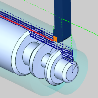
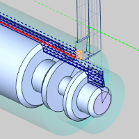
Operation Stock
Every operation that uses a tool, contains Operation Stock below it. Operation Stock tracks the effect of previous operations and displays a cutaway view of the current state of the stock. To utilize the Operation Stock, select the Trim to Stock option in the Parameters page of an operation.
 Operation Stock
-
Re/Select -
-
Remove - eliminates any selected geometry and returns to default.
Note: The icon shows the Operation Stock is set to default. The
default Operation Stock tracked based on the order of the operations as
they will occur at the machine, not the order of the features in the CAM
Tree. To review the order of operations as they will be called, right-click
on The Turning Job and click Machining
Order.
Related Topics
To find out more about features and operations, go to The Lathe Wizard Overview.