 Clearance for tool parts
Introduction
The Clearance for tool parts dialog box allows you to set the type of clearance, the clearance values, and the angular clearance to be used in case of gouge detection.
Clearance type
![]() Cylindrical - will define a cylindrical
boundary around each of the specified components with the values specified
below.
Cylindrical - will define a cylindrical
boundary around each of the specified components with the values specified
below.
Clearance values - define the clearance area around each of the individual components.
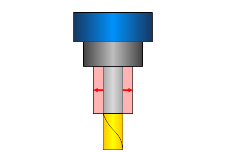
Shaft - sets the perpendicular distance from the shaft that will define the cylindrical clearance area around it.
![]() Click
here to see an example of Shaft Clearance
Click
here to see an example of Shaft Clearance
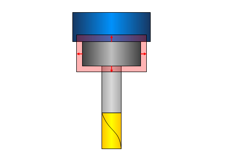
Arbor - sets the perpendicular distance from the arbor that will define the cylindrical clearance area around it.
![]() Click
here to see an example of Arbor Clearance
Click
here to see an example of Arbor Clearance
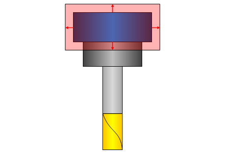
Holder - sets the perpendicular distance from the holder that will define the cylindrical clearance area around it.
![]() Click
here to see an example of Holder Clearance
Click
here to see an example of Holder Clearance
![]() Conical
- will define a conical boundary around
each of the specified components with the values specified below.
Conical
- will define a conical boundary around
each of the specified components with the values specified below.
Clearance values - define the clearance area around each of the individual components.
Shaft - defines the conical clearance area around the shaft.
Lower Offset - sets the perpendicular distance from the bottom of the shaft to define the conical clearance area.
Upper Offset - sets the perpendicular distance from the top of the shaft to define the conical clearance area.
![]() Click
here to see an example of Conical Shaft Clearance
Click
here to see an example of Conical Shaft Clearance
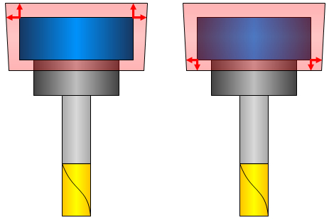
Arbor - defines the conical clearance area around the arbor.
Lower Offset - sets the perpendicular distance from the bottom of the arbor to define the conical clearance area.
Upper Offset - sets the perpendicular distance from the top of the arbor to define the conical clearance area.
![]() Click
here to see an example of Conical Arbor Clearance
Click
here to see an example of Conical Arbor Clearance
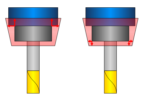
Holder - defines the conical clearance area around the holder.
Lower Offset - sets the perpendicular distance from the bottom of the holder to define the conical clearance area.
Upper Offset - sets the perpendicular distance from the top of the holder to define the conical clearance area.
![]() Click
here to see an example of Conical Holder Clearance
Click
here to see an example of Conical Holder Clearance
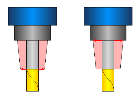
Angular clearance - creates a conical clearance area around the tool. The angles origin varies based on the type of tool selected. In the case of a flat end mill, the angle will originate from the bottom diameter of the tool. In the case of an end mill with a radius, the angle will originate from the tangency of the radius.
![]() Click here to see an example of
the Angular clearance
Click here to see an example of
the Angular clearance
When using
Angular clearance in conjunction with clearance values, clearance values
will extend the area of angular clearance. ![]() Click here to
see an example.
Click here to
see an example.