Using the Remnant
Introduction
Once a remnant sheet is saved from the nesting job, opened and cut free from the nested sheet there is only one step left before you can use that sheet in a nest. In this example we will use the remnant sheet we saved from our last job to nest more parts.
Example File
In this example we use the Remnant-Sheet-1-1.dxf file that was created from the Remnant Creation Example tutorial. If you have not gone through that tutorial yet, please take a moment to do so.
Part 1) Opening the Remnant
Normally when remnants are created and saved they are for future jobs. However, if you have just finished with the Remnant Sheet Creation Example, you probably still have the Remnant-Sheet-1-1.dxf file from Part 3 open. Either way, the first step to using any remnant is to have it open in BobCAD-CAM so that we can use it to nest more parts.
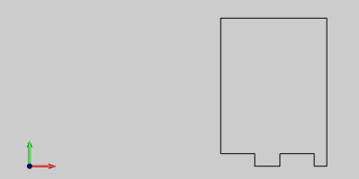
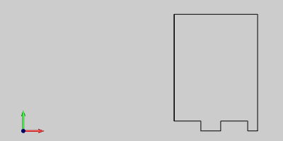
Navigate to your C:\BobCAD-CAM Data\BobCAD-CAM V** folder and open Remnant-Sheet-1-1.dxf.
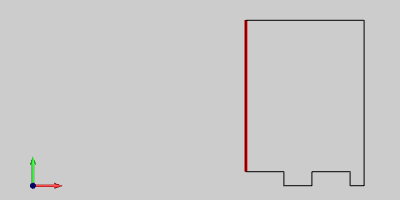
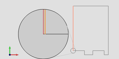
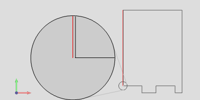
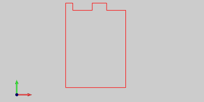
The first thing to keep in mind is that we cut this shape out. Every cut has a width to it. When we cut this remnant out in the last tutorial we cut the line with no compensation, which removed material from the left and the right of the line. Note in the image below, this is shown in red.
Cut Line | Cut Line Magnified |
|
|
In a nest with little to no margin, not taking this cut into account could ruin parts.
Part 2) Correcting the Geometry
We will take a moment to update the geometry to reflect the material that was removed from the remnant shape when we freed it from the sheet.
In the Entity group, of the Create 2D ribbon, click the down arrow under
 Line and click
 Line Parallel.
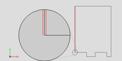
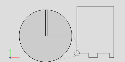
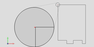
Since we used a 0.2500 inch diameter tool to cut free the sheet, set the Distance value to 0.1250.
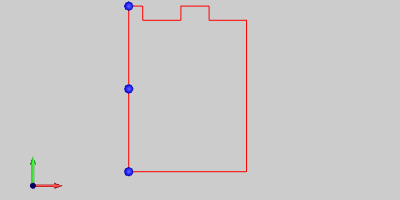
Click on the vertical line to the left, drag your mouse a little to the right, to choose the right side of the line to create the parallel line, and click your mouse again to finalize.
Parallel Line Preview | Parallel Line Preview Magnified |
|
|
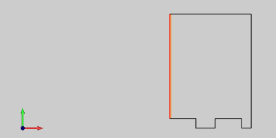
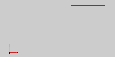
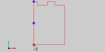
Now that we have created the proper line, we need to trim off the remainder. In the Trim Extend group of the Utilities ribbon, click
 Quick Trim.
Parallel Line | Parallel Line Magnified |
|
|
Now that we have the
Quick Trim feature
active, click the segments that need to be eliminated. 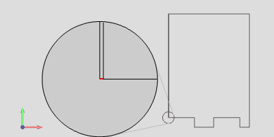
Part 3) Rotating the Geometry.
The WCS in the CAD window will also be our Machine Zero for the nest. We need to move this sheet to place it in relation to the WCS as the actual sheet will be to the machine zero. We will have the top left of our sheet as our origin and nest in the X+,Y+ quadrant. In order to accomplish this, we will need to rotate the part 180º and move it to the WCS.
In the Move group of the Utilities ribbon, click
 Rotate.
Hover your mouse over one of the lines of our remnant shape, hold shift on your keyboard and then left-click to chain-select the entire chain. The entire chain should now be highlighted.
Press the Spacebar on your keyboard or right-click inside of the CAD window and select
 OK to finalize
geometry selection.
OK to finalize
geometry selection. 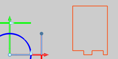
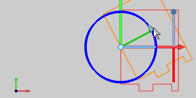
The rotation sketch handles appear and we now need to define the degree of rotation and the center of that rotation. This can be done using the data entry or the sketch handles themselves. We will use the sketch handles in this lesson. First, click the center of the sketch handles to alter its origin.
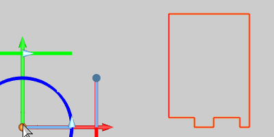
You are now free to move your mouse around to alter the origin of rotation. Hover your mouse over the middle of the left line of the remnant shape and left-click.
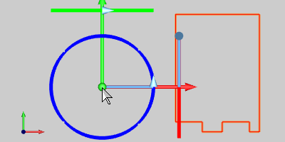
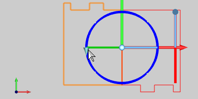
Left-click the arrow on the blue, X axis rotation handle to alter the degree of rotation.
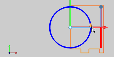
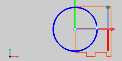
Bring the handle counter-clockwise to the 180º location, left-click once to set that location, then press the Spacebar on your keyboard to finalize.
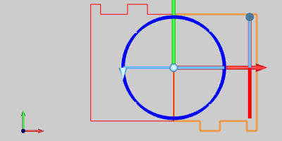
Cancel out of the
Rotate
feature. 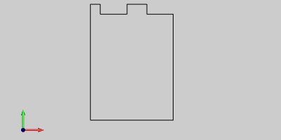
Part 4) Translating the Geometry
Now that we have the geometry rotated the way we will want it on our machine, we need to move it the rest of the way to the WCS.
In the Move group, of the Utilities ribbon, click
 Translate.
Select the Sketch/Enter option at the top. This will allow us to set the Start point with a Pick or Enter method. This will also allow us to set the End point with a Pick or Enter method. By default, the Sketch/Enter option will be set to Pick the start point and Enter the End value. Also by default, the End value will be set to X 0.0000, Y0.0000, Z0.0000. This is convenient for us since that is where we want to place the corner of our shape.
Hover your mouse over one of the lines of our remnant shape, hold shift on your keyboard and then left-click to chain-select the entire chain. The entire chain should now be highlighted.
The next step in the translation process is to pick the start point. Since we have the end point set to Enter, the next point we pick will be translated to X 0.0000, Y0.0000, Z0.0000. Hover your mouse over the line on the left of the shape, hold shift on your keyboard and left-click it once to display the snap points.
Left-click the snap point on the bottom.
Our remnant shape is now aligned with the WCS as we will have it set to the Machining Origin on our machine. Press cancel to exit the
 Translate
function.
Translate
function. 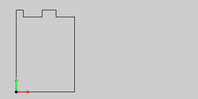
Part 5) Creating the Nesting Job
Now that the sheet is in the proper orientation, we can create our nesting
job and use that as our stock.
In the CAM Job group, of the CAM ribbon, click
 New CAM Job.
Select Nesting as our Job Type and then click the Nesting Wizard button.
Part 6) Load Files
When it comes to picking geometry you can either select geometry that is already open in your CAD window, load geometry from existing files that have not yet been open, or a combination of both. In this case, we will load files.
Click the Load Files button.
Navigate to your C:\BobCAD-CAM Data\BobCAD-CAM V**\Examples folder and select Hole_Dado_Tutorial.bbcd.
Since the hole and dado geometries were separated to their own layer, and named properly, they have automatically been assigned to the proper operational groups. Click OK.
Click Next>> to move on to the
 Part Parameters page.
Part 7) Setting Part Parameters
Now that the parts are all loaded, and the layers have been automatically organized, we will set some basic part parameters.
We only want to nest the first two parts, so click on Part 3 to highlight it, hold Ctrl on your keyboard and left-click Part 4 highlight it as well.
Click the Remove button and then the Yes button to remove these from the Part List.
Fill out the part quantities to match the following values.
Part Name | Quantity |
Part 1 Part 2 | : 4 : 4 |
We will be leaving the other settings at default. Click Compute at the bottom left of the wizard.
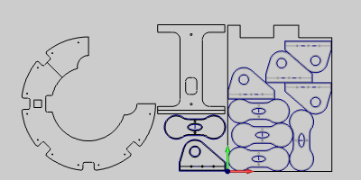
Part 8) Checking the Result
Now that the nest has been regenerated, we will want to check to see if the change we made to the Nesting Parameters has helped eliminate leftover parts.
In the CAM Tree, right-click on
 Sheets and select Show Summary. Here we can see we have no leftover parts.
Click OK at the bottom of the Nesting Summary to close it.
Part 9) Simulating
Now that the nest has been generated and all the parts fit on the sheet, we will check the simulation to visualize the machining order prior to posting the code.
Right-click on the Nesting Job and select Simulation to enter into the simulator to check the final result. Learn more about the simulation here.
Part 10) Posting the Program
Once the nested result has been finalized it will be time to produce
the code to send to the machine.
In the CAM Tree, Click the plus symbol next to
Sheets to show its contents. Click the plus symbol next to
 Sheet-1 to show its contents.
Right-click
Sheet-1-1
under the main Sheet-1 sheet type and select Post Sheet. The code is posted in the Layer-UCS-Post Manager.
Right-click on the code in the Layer-UCS-Post Manager to select Save As or Edit CNC. With this method, you can either save to a particular file location or to open in Predator Editor respectively.
This concludes this tutorial.