 Arc 2 Points - Diameter
Introduction
This topic will explain the Arc 2 Points - Diameter function, will explain where to find the function, and explain the options found in it. This topic will also give a brief description of Dynamic Drawing, the Snap Increment function, explain creation with quick steps and examples, and provide links to related topics.
The Arc 2 Points - Diameter Function
The Arc 2 Points - Diameter function is used to create arcs of a specified radius, and start and end angles, by defining two points in the graphics area which will become the full diameter of the arc. This can be accomplished by picking two points or snap points in the graphics area, and altering the data entry information as needed.

Dynamic Drawing
This function supports Dynamic Drawing which allows you to use a combination of sketching and data entry to create the entities. After initially sketching the entity, it becomes an active entity, which is an entity that is in Modify Mode. Entities in Modify Mode display in the current Entity color, but displays with a greater line thickness to make them easier to identify. Active entities can be modified using data entry. The benefit of Dynamic Drawing is that you can quickly sketch a point to get the approximate result and then use data entry to update to the exact dimensions, and coordinate values as needed.
|
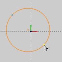
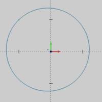
Entities in Modify Mode |
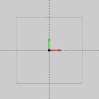
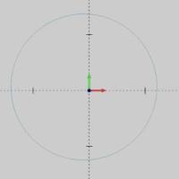
Final Entities |

|
|
In the images above, we see entities which are still in Modify Mode, followed by those same entities after they are finalized.
Snap Increment
This function support the use of the snap increment when selecting the location of the entities. The snap increment allows you to get precise results when using mouse selection and helps to reduce data entry modifications.
To learn more, view Snap Increment.
Navigation
To open Arc 2 Points - Diameter:
-
In the Entity group, of the Create 2D ribbon, click the down arrow under
 Arc, and select
  Arc 2 Points - Diameter.
The parameters display in the Data Entry Manager.
The Data Entry Parameters
 Creation Option
![]()
![]()
![]()
![]()
![]()
![]()
![]()
Parameters
Center
- X - sets the location of the arc center along the X axis.
-
Y - sets the location of the arc center along the Y axis.
-
Z - sets the location of the arc center along the Z axis.
Dimensions
-
Radius - sets the distance from the center of the arc to the circumference.
-
Start Angle - sets the rotation angle at which the arc begins measured from the positive X-axis.
-
End Angle - sets the rotation angle at which the arc ends measured from the positive X-axis.
-
Other Half - allows you to choose the other half of the specified angle range.
- OK - finalizes the function.
- Cancel - exits the function.
Quick Steps - Arc 2 Points - Diameter
-
Open
the function and click a snap point or anywhere in the graphics area
to set the first of two points which will define the diameter.
You can modify the snap increment value or turn it off while selecting the points of the diameter.
- Move the mouse pointer
and click a snap point or anywhere to set the final point of the arc
diameter.
The arc changes from the Preview color to the Entity color and displays with a greater line thickness to show it is the active entity.


- With Dynamic Drawing, you can update the
Data Entry parameters to modify the active entity, or you can continue
sketching.
If you continue sketching, the active entity is automatically finished. - After updating the Data Entry parameters,
to finish the active entity, you can either click OK or you can click the next point to begin creation of a new arc.

- Repeat this process of using sketching and
data entry to create arcs as needed.
- To close the function, click Cancel.
Examples
Example 1 (Using Two Points)
- In the Quick Access Toolbar, click
 New.
New. -
In the Entity group
of the Create 2D ribbon, click
 Point.
 - Point to any location In the graphics area, and click
to create a point.


- Point to any other location, and click to create a second point.


- In the Entity group, of the Create 2D ribbon, click the down arrow under Arc, and select Arc 2 Points - Diameter.
- In the graphics area, point to either point so that
it changes to the Highlight color, and click to select it.

The CAD preview displays and updates as you move the mouse pointer.
- Point to the other point, so it displays in the Highlight color,
and click to select it.
Important: When selecting the snap points for this function, it is important to assure that the entity is highlighted when you click it. If you click an arbitrary location in the graphics area, the position that you click is used (this function uses either the snap points or the screen position that you click).
The circle is created between the two defined points.

- To end the function, in the Data Entry Manager, click Cancel.
Note: For this example, we used two point entities to create the circle. You are not limited to using point entities with this function, you can use the snap points of any entities in the graphics area, for example, of a line or an arc. This is shown in the following example.
Example 2 (Using Two Snap Points)
- In the Quick Access Toolbar, click New.
-
In the Shapes group, of the Create 2D ribbon,
click
 Rectangle.
 - In this case, we will create a rectangle using the default values.
Click OK to create the default rectangle as shown in the CAD preview.

-
In the Entity group, of the Create 2D ribbon, click the down arrow under Arc, and select Arc 2 Points - Diameter
- In the graphics area, point to either the horizontal line or the vertical line near the top-left corner of the rectangle so that it changes to the Highlight color.

Notice that once it is highlighted, the snap points appear. 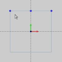
- Hover over the snap point, as seen in the image below to highlight it.
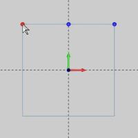
- With the snap point highlighted, click it and begin to drag your mouse to the opposite corner of the rectangle.
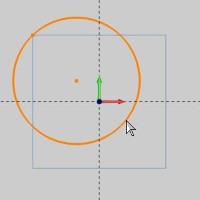
Notice a preview of the circle is shown. - Hover of the vertical line on the left, long enough to highlight it, and the snap points will appear as shown below.


- Highlight the lower snap point and click on it.


The arc is created, but remains in modify mode. This allows you to adjust any of the parameters in the Data Entry Manager prior to finalizing the arc. - Click OK.

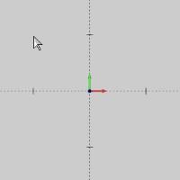
The arc is created. - Click Cancel to exit the function.
Example 3 (Sketch Method)
-
In the Entity group, of the Create 2D ribbon, click the down arrow under Arc, and select Arc 2 Points - Diameter
- Point to any location in the graphics area, and click
to set the first point of the circle.
As you move the pointer away from the first point, the CAD preview of the circle is updated.
- Point to any location in the graphics area, and click
to set the second point and create the circle.

Once the second location is selected, the preview disappears and the arc is shown in modify mode. This mode allows you to update the parameters as needed before finalizing the arc. - Click OK to finalize the arc.
- To end the function, click Cancel.
This concludes the examples.