Arc 3 Entities
Introduction
This topic will explain the Arc 3 Entities function, will explain where to find the function, and explain the options found in it. This topic will also explain creation with quick steps and examples, and provide links to related topics.
The Arc 3 Entities Function
The Arc 3 Entities function is used to create arcs by selecting 3 entities in the graphics area which will create an arc tangent to each. This can be accomplished by picking three entities in the graphics area.

Navigation
To open Arc 3 Entities:
-
In the Entity group, of the Create 2D ribbon, click the down arrow under
 Arc, and select
  Arc 3 Entities.
The parameters display in the Data Entry Manager.
The Data Entry Parameters
 Creation Option
![]()
![]()
![]()
![]()
![]()
![]()
![]()
Entity Selection
Selected Geometry
|
|
|
| The list box will list the entities currently selected for the function. | |
 (Delete All)
- removes all entities from the list.
(Delete All)
- removes all entities from the list.
- OK - finalizes the function.
- Cancel - exits the function.
Quick Steps - Arc 3 Entities
-
Open
the function and click the first wireframe entity to set the first
of three entities to be used in the creation of the arc.

- Move the mouse pointer
and click the second wireframe entity.

- Move the mouse pointer and click the third
wireframe entity.

The preview appears. - To finish the active entity, click OK.
- Repeat this process to create arcs as needed.
- To close the function, click Cancel.
Examples
Example 1
- In the Quick Access Toolbar, click
 New.
New. -
In the Entity group
of the Create 2D ribbon, click
 Point.
 - Place three points anywhere in the graphics area.
-
In the Entity group, of the Create 2D ribbon, click the down arrow under Arc, and select Arc 3 Entities.
- Left click on one of the three
points created previously.
- Left click on another of the three
points created previously.
- Left click on the last of the three
points created previously.
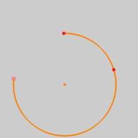
With 3 entities selected, the preview is displayed.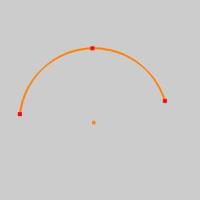
The order of the entities also helps determine the result, but the order can also be adjusted in the Selected Geometry list. - Click the first entity listed in the Selected Geometry list.
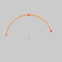
The entity highlights in the graphics area. - Use the arrows next to Selected Geometry list to adjust its position in the list.
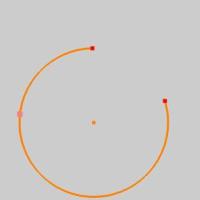
- Click OK when the desired result is shown in the preview.

The arc is created. - Click Cancel to exit the function.
Example 2
- In the Quick Access Toolbar, click New.
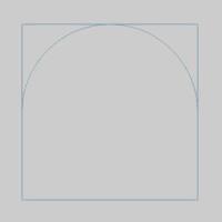
- In the Shapes group, of the Create 2D ribbon,
click
 Rectangle.
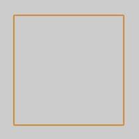
The preview shows the rectangle that would be created with default settings.
- Leave the default settings for the Rectangle, and click OK.
The finalized rectangle is created, and the preview remains showing what the current settings would create. - In the Entity group, of the Create 2D ribbon, click the down arrow under Arc, and select Arc 3 Entities.

The rectangle preview disappears. - Select 3 sides of the rectangle, either by clicking on them individually, or using a window pick.
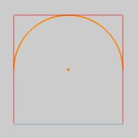
The preview appears.
The order of the selected entities can be adjusted in the Selected Geometry list as seen in the last example if necessary. - Click OK to create the arc.