 Arc Fit Arcs
Introduction
This topic will explain the Arc Fit Arcs function, will explain where to find the function, and explain the options found in it. This topic will also give a brief description of Dynamic Drawing, the Snap Increment function, explain creation with quick steps and an example, and provide links to related topics.
The Arc Fit Arcs Function
The Fit Arcs function converts a selected geometry curve into arc segments using a defined tolerance value.
Navigation
To open Fit Arcs:
-
In the Entity group, of the Create 2D ribbon, click the down arrow under
 Arc, and select
  Fit Arcs.
The parameters display in the Data Entry Manager.
The Data Entry Parameters
 Creation Option
![]()
![]()
![]()
![]()
![]()
![]()
![]()
Entity Selection
Tolerance - sets the amount of variation allowed when creating the fit arcs.
Selected Geometry
|
|
|
| The list box will list the entities currently selected for the function. | |
 (Delete All)
- removes all entities from the list.
(Delete All)
- removes all entities from the list.
-
OK - creates the active arc entity after using data entry.
-
Cancel - closes the Data Entry Manager.
Quick Steps - Arc Fit Arcs
-
Open the function and set
the tolerance to use for the creation of the arcs.
- Select the items in the graphics
area to apply the Fit Arc function to.

The items are added to the Selected Geometry list. - Click
OK.


The Results dialog displays with a report on the number of arcs created. - Click
OK to close the Result dialog.
- Repeat
this process as needed.
- To close the function, click Cancel.
Example
This example will demonstrate how to use the Fit Arcs function.
Note: In the images below, both the Show Axis X-Y and Show Gnomon toggles have been disabled in the Axis X-Y group of the Settings Part > Display dialog.
- In the Shapes group, of the Create 2D ribbon, click
the
 Shape Library icon.
The Data Entry Manager is populated with the parameters of the Disk. - In the Data Entry Manager, click on the image of the Disk.
The Shape Library dialog launches, allowing you to select from the library shapes. - Select the
 (Polygon Inner) icon and click OK.
The parameters open in the Data Entry manager, and the Preview displays.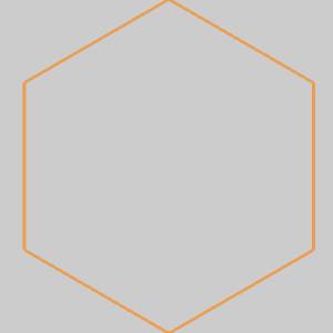
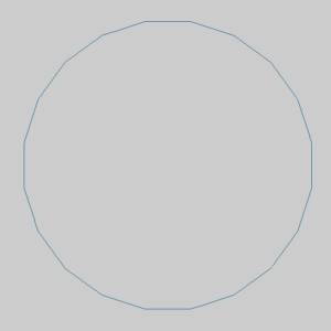
- Enter 20 for
the Number of Sides value.
The Preview updates.
- Click OK to
confirm the settings and placement of the Polygon Inner.
The Polygon Inner is created in the graphics area, and the Polygon Inner feature is added to the CAD Tree. - In the Entity group, of the Create 2D ribbon, click the down arrow under Arc, and select Fit Arcs.
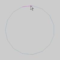
- Notice the Tolerance value is set 0.0004.
Click anywhere in the graphics area to give it focus, and press Ctrl+A on your keyboard to use the shortcut for Select All.
The entities are selected. - Click OK to confirm.
A dialog appears with the message: Arc fit result will return more entities than started with, you may want to increase the tolerance, would you like to continue? - Click Yes.
The Results dialog appears showing: Arcs Created 14 - Click OK.
The result displays in the graphics area. In this case, the results are not obvious. - Click anywhere in the graphics area to give it focus, and press
Ctrl+Z on your keyboard to
Undo the Arc Fit.
Note: If the Undo command is used one too many times, the Polygon Inner will be undone as well. If this occurs, simply use CTRL+Y (Redo) to bring it back.
- Change the Tolerance value
to 0.0040.
Click anywhere in the graphics area to give it focus, and press Ctrl+A on your keyboard to use the shortcut for Select All.
The entities are selected. - Click OK to confirm.
A dialog appears with the message: Arc fit result will return more entities than started with, you may want to increase the tolerance, would you like to continue? - Click Yes.
The Results dialog appears showing: Arcs Created 1 - Click OK.

Again, the result displays in the graphics area. The results are still not obvious. - Click anywhere in the graphics area to give it focus, and press
Ctrl+Z on your keyboard to
Undo the Arc Fit.
- Change the Tolerance value
to 0.040.
- Click anywhere in the graphics area to give it focus, and press
Ctrl+A on your keyboard to
use the shortcut for Select All.
The entities are selected. - Click OK to confirm.
The Results dialog appears showing: Arcs Created 1 - Click OK.

The result displays in the graphics area, and this time we can see a single arc has been created. - To end the function, click Cancel.
This concludes the example.