 Radius Dimension
Introduction
This topic will explain the Radius Dimension function, will explain where to find the function, and explain the options found in it. This topic will also give a brief description of creation with quick steps and an example, and provide links to related topics.
Note: Though there are separate topics for each dimension topic, the Data Entry Parameters used in the functions are all the same.
The Radius Dimension Function
The Radius Dimension function is used to create a dimension on a radius in the graphics area. This can be accomplished by picking a wireframe arc, and altering the data entry information as needed.
Navigation
To open Radius Dimension:
-
In the Dimensions group, of the Evaluate ribbon, click
 Radius.
The parameters display in the Data Entry Manager.
The Data Entry Parameters
 Creation Option
![]()
![]()
![]()
![]()
![]()
![]()
![]()
Font
- Font - Select a font type: Windows Font or BobCAD Font.
- Font List - Click the arrow to select the font from the list.
- Height - sets the height of the text on the created dimension.
Selected Geometry
|
|
|
| The list box will list the entities currently selected for the function. | |
 (Delete All)
- removes all entities from the list.
(Delete All)
- removes all entities from the list.Dimension
-
Decimals - sets the number of decimal places, or digits after the decimal point, displayed in the dimension text. These are only displayed for values that aren't whole numbers, unless Extra Zeroes are selected.
-
Scale - sets the scale of the measured dimension. A value of one means no scaling or 100 percent of the actual size of the entity. A value of 0.5 means that when you place a dimension on a line that is two units long, the dimension displays a value of one unit.
- Extra Zeroes - determines whether trailing zeros are used.
![]() - Trailing
zeros are not used. As an example, if a value of four is used for the
Decimals option, a dimension of 1.1 would appear as 1.1 in the graphics
area.
- Trailing
zeros are not used. As an example, if a value of four is used for the
Decimals option, a dimension of 1.1 would appear as 1.1 in the graphics
area.
![]() - Trailing
zeros are used. As an example, if a value of four is used for the Decimals
option, a dimension of 1.1 would appear as 1.1000 in the graphics area.
- Trailing
zeros are used. As an example, if a value of four is used for the Decimals
option, a dimension of 1.1 would appear as 1.1000 in the graphics area.
Tolerance
|
|
None | - does not show any tolerance values after the initial dimension. |
| Single | - shows only one tolerance value. This value is listed as a positive value unless otherwise specified. | |
| Symmetric | - shows only one tolerance value. This value is listed with a positive and negative symbol in front of it to show the tolerance range. | |
| Custom | - shows two tolerance values. These values are listed as positive values unless otherwise specified. |
- Extra Zeroes - determines whether trailing zeros are used.
![]() - Trailing
zeros are not used. As an example, if a value of four is used for the
Decimals option, a dimension of 1.1 would appear as 1.1 in the graphics
area.
- Trailing
zeros are not used. As an example, if a value of four is used for the
Decimals option, a dimension of 1.1 would appear as 1.1 in the graphics
area.
![]() - Trailing
zeros are used. As an example, if a value of four is used for the Decimals
option, a dimension of 1.1 would appear as 1.1000 in the graphics area.
- Trailing
zeros are used. As an example, if a value of four is used for the Decimals
option, a dimension of 1.1 would appear as 1.1000 in the graphics area.
Text Options
The Text Options group is used to display custom text in the dimension. The chevron to the left will also allow you to collapse and expand the entire group.
-
Pre - type text in this box and it is placed before the displayed dimension text.
-
Post - type text in this box and it is placed after the displayed dimension text.
- Text Orientation - this toggle will allow you to switch the dimension text from a Angle to a Angle orientation.
Arrows
Style
-
Left - By default the Left option will be set to the arrow style currently used in the Part Settings dialog. However, the Left option allows you to update the arrow style on the fly without going to the Part Settings dialog to do so.
- Right - By default the Right option will be set to the arrow style currently used in the Part Settings dialog. However, the RIght option allows you to update the arrow style on the fly without going to the Part Settings dialog to do so.
-
Auto - places the arrows on the inside of the witness lines, unless the listed value and the arrows overlap. If the listed value and the arrows would overlap, the arrows will automatically be shifted to the outside of the witness lines.
-
Out - places the arrows on the outside of the witness lines.
-
In - places the arrows on the inside of the witness lines
-
Width - sets the width of the arrows being used.
-
Length - sets the length of the arrows being used.
Position
When creating dimensions by selecting snap points, Left refers to the first point, and Right refers to the second point:
- Both - two arrows are used, with one pointing to each witness line.
- Left - one arrow points to the left witness line.
- Right - one arrow points to the right witness line.
- None - no arrows are used.
- OK - finalizes the function.
- Cancel - exits the function.
Quick Steps - Radius Dimension
- Open the function.
The Selected Geometry list automatically has focus. - Select the item to be dimensioned.
The item is added to the Selected Geometry list.
The dimension preview appears and its position follows the cursor. - Move the cursor to position the dimension roughly into the area of intended placement, and click to temporarily set its placement.
- Adjust the parameters in the Data Entry Manager to achieve the desired font, text size, listed values etc.
- If the updated style of the dimension calls for its position to be moved, move your cursor into the graphics area above the dimension value, until the dimension highlights.
- Click the highlighted dimension.
The dimension is able to be relocated. - Move the dimension into its final placement.
- Click to set placement.
- Click OK to finalize.
- Repeat as necessary.
- Click Cancel to exit the function.
Example
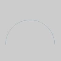
-
In the Dimensions group, of the Evaluate ribbon, click
Radius.
The parameters launch in the Data Entry Manager, and the Selected Geometry list automatically has focus to allow for the selection of geometry.Tip: This can also be accomplished with the
 Auto dimension function.
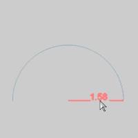
 - Hover over the arc and select it.

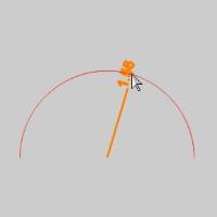
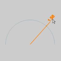
The entity is added to the Selected Geometry list, and the preview is immediately visible. - Use the mouse to move the dimension into position, and click to set it.
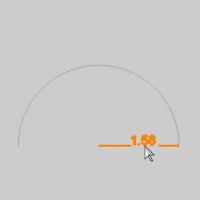
The dimension still appears as a preview.
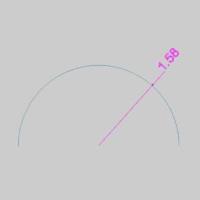
Clicking OK, or Cancel at this point would finalize the location of the Dimension. - Hover over the dimension and click on it.
The location of the dimension can be adjusted again. - Click to set the dimension location.
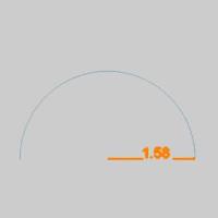
- Click OK.
The dimension is set, and another can be created. - Repeat as necessary.
- Click Cancel to exit the function.