 Line Angle
Introduction
This topic will explain the Line Angle function, will explain where to find the function, and explain the options found in it. This topic will also explain creation with quick steps, an example, and provide links to related topics.
The Line Angle Function
The Angle function creates a line at an angle to a selected entity. To perform the function, you define the parameters in the Data Entry Manager, and then select wireframe geometry in the graphics area.
Navigation
To open Line Angle:
-
In the Entity group, of the Create 2D ribbon, click the down arrow under
 Line and click
  Line Angle.
The parameters display in the Data Entry Manager.
The Data Entry Parameters
 Creation Option
![]()
![]()
![]()
![]()
![]()
Parameters
Angles and Length
- Angle - sets te angle at which the line is created based on the selected mode. When using Absolute or Tangent, this is measured from the positive X axis of the Active UCS. Relative to Entity is measured from the start or end of the selected entity.
- Length - sets the length of the line to be created.
- Angle Z Axis - sets the angle from the Z axis at which the line is created.
Angle Option
-
 Angle Relative to Entity - creates
the line using the selected entity as the reference for the angle.
The following two option become available.
Angle Relative to Entity - creates
the line using the selected entity as the reference for the angle.
The following two option become available. -
 Absolute - always creates the line using both the Angle and Angle to Z Axis
parameters in reference to the Active UCS.
Absolute - always creates the line using both the Angle and Angle to Z Axis
parameters in reference to the Active UCS. -
Tangent - creates
a line tangent to an arc entity with the angle measured from the X-axis
of the Active UCS. The location that you click on the arc determines
the direction of the line. You can point to either end of the arc
or start point of a circle, to view the CAD preview of the line.
Start/End Option
-
Use As Start - sets the point to be selected as the start of the angle.
-
Use As End - sets the point to be selected as the end of the angle.
-
OK - has no use with this function.
- Cancel - closes the Data Entry Manager.
Quick Steps - Line Angle
-
Open the function and define all Data Entry
parameters.
- Hover over a wireframe entity to display the
CAD preview of the line.
Click the snap point of a wireframe entity to create a line. -
Update Data Entry parameters if you want
to create another line.
-
Repeat this process as needed.
- To close the function, click Cancel
Example
- In the Quick Access Toolbar, click
 New.
New. - In the Shapes group, of the Create 2D ribbon,
click
 Rectangle.
The Data Entry Manager is populated with the parameters of the Rectangle function.
The preview appears, showing the results of the default settings.
- Leave the default Dimensions, but adjust the Base Point X value to 1.125.
- Click OK.
The rectangle is created, and the preview remains. - In the Entity group, of the Create 2D ribbon, click the down arrow under
 Arc, and select
  Arc Center.
The Data Entry Manager is populated with the parameters of the Arc Center function.
The preview appears, showing the results of the default settings.
- Adjust the Center X value to -1.125.
- Adjust the Dimensions:
Radius: 1.000
Start Angle: 10.000
End Angle: 370.000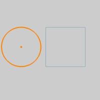
- Click OK.

- In the Entity group, of the Create 2D ribbon,
click the down arrow under Line and click Line Angle.
The Data Entry Manager is populated with the parameters of the Line Angle function.
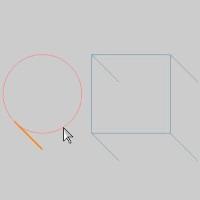
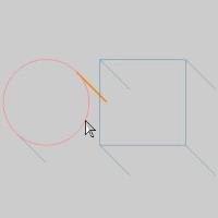
In this example, we will be creating the angled lines, which are seen in the image below.
These lines run along the 135° / 315° angle when referenced to the UCS, but along the vertical lines of the rectangle, it is a 45° angle. - With the parameters left at their default values, hover over the bottom, then the top of the arc.


The Angle Option "Angle Relative to Entity" sets the line at the beginning or end of an entity, which will not work for our arc. - Hover over the top line of the rectangle.
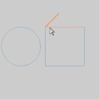
Our Point Usage Option is currently set to Use As Start, which will not work with the top line. - Hover over the top half of the vertical line, as shown in the image below.
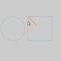
Using this method, we could create two of our angles, by selecting the top half of the two vertical lines. - Hover over the bottom half of the vertical line.
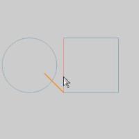
- Update the Point Usage Option to Use As End, and hover over the same area.
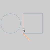
Switching between these two options would work, but we want to achieve the same angle regardless of the entity we select, so lets use Absolute angles. - Update the Angle Option to Absolute.
- Set the Angle value to 315.
- Click each corner of the rectangle.

Notice also, if you hover over the middle of a line, a preview is shown. This shows a line angle can be created from the beginning, middle, or end of an entity. - Update the Angle Option to Tangent.
- Click each side of the arc, near where the lines should be.
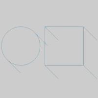
The line angles are created at then tangency point on the arc.
That concludes this example.