 Line Continuous
Introduction
This topic will explain the Line Continuous function, will explain where to find the function, and explain the options found in it. This topic will also give a brief description of Dynamic Drawing, the Snap Increment function, explain creation with quick steps, and provide links to related topics.
The Line Continuous Function
The Line Continuous function is used to create lines by clicking in the graphics area once to define the start point and clicking a second time to define the end point of the line. You can use the snap points of other wireframe entities to define these locations. When using the Continuous After creating the first line, the end point of the previous line becomes the start point of the next line so that you can create a continuous chain of line entities.
Dynamic Drawing
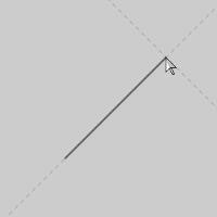
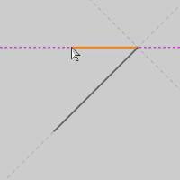
This function supports Dynamic Drawing which allows you to use a combination of sketching and data entry to create the entities. After initially sketching the entity, it becomes an active entity, which is an entity that is in Modify Mode. Entities in Modify Mode display in the current Entity color, but displays with a greater line thickness to make them easier to identify. Active entities can be modified using data entry. The benefit of Dynamic Drawing is that you can quickly sketch a point to get the approximate result and then use data entry to update to the exact dimensions, and coordinate values as needed.
|
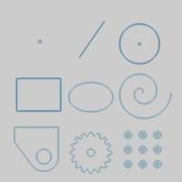
Entities in Modify Mode |
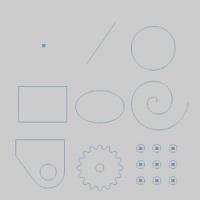
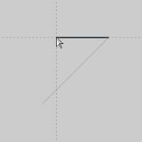
Final Entities |
|
|
In the images above, we see entities which are still in Modify Mode, followed by those same entities after they are finalized.
Snap Increment
This function support the use of the snap increment when selecting the location of the entities. The snap increment allows you to get precise results when using mouse selection and helps to reduce data entry modifications.
To learn more, view Snap Increment.
Navigation
To open Line Continuous:
-
In the Entity group, of the Create 2D ribbon, click the down arrow under
 Line and click
 Line Continuous.
The parameters display in the Data Entry Manager.
The Data Entry Parameters
 Creation Option
![]()
![]()
![]()
![]()
![]()
Parameters
Line
-
Length - while the start point is being set, the Length option is unavailable.
-
Angle - while the start point is being set, the Length option is unavailable.
Start Point
Absolute
- X- allows you to manually set the start point location along the X axis.
- Y- allows you to manually set the start point location along the Y axis.
- Z- allows you to manually set the start point location along the Z axis.
Note: to set the start point manually, you must enter a value. When the values are altered, a point will appear in the graphics area in modify mode. To confirm this start point, click OK. With the Start Point set, the End Point takes over.
Line
-
Length - sets the length of the line currently in modify mode.
-
Angle - sets the Angle of the line currently in modify mode.
-
 Abs - sets the angle to an incremental angle.
 -
 Abs - sets the angle to an absolute angle based on the current UCS in use.
End Point
Absolute
- X- allows you to manually set the end point location along the X axis.
- Y- allows you to manually set the end point location along the Y axis.
- Z- allows you to manually set the end point location along the Z axis.
Note: to set the start point manually, you must enter a value. When the values are altered, a point will appear in the graphics area in modify mode. To confirm this start point, click OK. With the Start Point set, the End Point takes over.
Incremental
- X- allows you to manually set the end point location, from the start point, along the X axis.
- Y- allows you to manually set the end point location, from the start point, along the Y axis.
- Z- allows you to manually set the end point location, from the start point, along the Z axis.
Cursor Reference
-
Length - shows the length of the line currently previewed.
-
Angle - sets the Angle of the line currently previewed.
-
Abs - sets the angle to an incremental angle.
-
Abs - sets the angle to an absolute angle based on the current UCS in use.
Cursor Position
Absolute
- X- shows you absolute position of the cursor along the X axis.
- Y- shows you absolute position of the cursor along the Y axis.
- Z- shows you absolute position of the cursor along the Z axis.
Incremental
- X- allows you to manually set the end point location, from the start point, along the X axis.
- Y- allows you to manually set the end point location, from the start point, along the Y axis.
- Z- allows you to manually set the end point location, from the start point, along the Z axis.
- OK - finalizes the function.
- Cancel - exits the function.
Quick Steps - Line Continuous
Dynamic Drawing Method
-
Open the function and click a snap point or anywhere
in the graphics area to set the start point of the line.
The Start Point values update to the mouse location.
You can modify the snap increment value or turn it off while selecting start and end points.
When you move the pointer, the CAD preview displays, and the End Point values update relative to the current mouse position.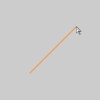
-
Click another location in the graphics area to set
the End Point of the first line, and the Start Point of the next.
This line is now an active entity, and its End Point, which is now the Start Point of the new line, can be adjusted by changing the values of the Start Point.
Tip: When you move the mouse pointer into the graphics area, the data entry values are updated to the current screen position. You should keep the mouse pointer in the Data Entry Manager, until you click OK, to avoid changing the Current Point values you have entered.
When you move the pointer, the CAD preview displays, and the End Point
values update relative to the current mouse position.
-
Click another location in the graphics area to set the End Point
of the previewed line, and the Start Point of the next.
-
Continue this process using any combination of sketching and/or
data entry to create a continuous chain of lines.
- To close the function, click Cancel.
Sketch Method
-
Open the function and click a snap point
or anywhere in the graphics area to set the start point of the line.
The Start Point values update to the mouse location.
You can modify the snap increment value or turn it off while selecting start and end points.
When you move the pointer, the CAD preview displays, and the End Point values update relative to the current mouse position. -
Click another location in the graphics area
to set the End Point of the first line.
This line is now an active entity, and its Start Point, and End Point, can both be adjusted by changing the values of the Start Point and End Point in the Data Entry Manager.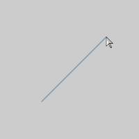
When you move the pointer, no CAD preview displays.
The line remains as an active entity until you click OK, or another point in the graphics area is selected to begin a new line.
Continue this process using any combination of sketching and/or data entry to create a the needed lines. - To close the function, click Cancel.