 Project Curves to Surface
Introduction
This topic will explain where to find the Project Curves to Surface function, and explain the options found in it. This topic will also give quick steps, an example, and provide links to related topics.
The Project Curves to Surface Function
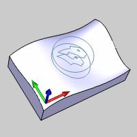
The Project Curves to Surface function projects wireframe curves onto a selected surface. The projection direction is always along the Z-axis of the Active UCS.

Navigation
To open Project Curves:
-
In the Utilitiesgroup, of the Create 2D ribbon, click
 Project Curves.
The parameters display in the Data Entry Manager.
The Data Entry Parameters
The function is performed using only geometry selection.
Select Curves to Project
|
|
|
| The list box will list the entities currently selected for the function. | |
|---|---|
 (Delete All)
- removes all entities from the list.
(Delete All)
- removes all entities from the list.
Select Surface/Solid
|
|
|
| This list box will show the entity currently selected for the function. | |
- OK - finalizes the function.
- Cancel - exits the function.
Quick Steps - Project Curves to Surface
- When the function is open, the Select Curves to Project list automatically has focus.
Click, drag a window, or chain select the wireframe entities that you want to project. - Click in the Select Surface/Solid list to put focus on this list.
- Select the surface or solid to project onto.
The surface, or solid is added to the list, and the preview appears showing the current result to be confirmed. -
Click OK to confirm the result.
-
Repeat this process as needed for any other curves
to project.
- To close the function, click Cancel.
Example
- In the Quick Access Toolbar, click
 New.
New. - In the Primitives group, of the Create 3D tab, click
 Sphere.
The preview appears.
- Leave the default values as they are and click OK.
The sphere is created.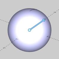
- In the Shapes group, of the Create 2D ribbon,
click
 Rectangle.
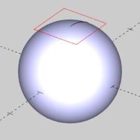
The sketch handles of the sphere function disappear. The preview of the rectangle appears.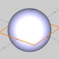
- Update the Dimension group values to Length 1.000, Width 1.000.
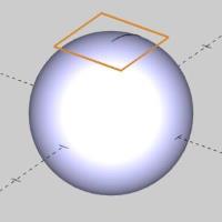
- Update the Base Point Z value to 1.000.

- Click OK.
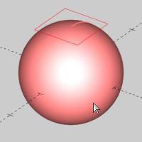
- At the bottom right of the screen, click the down arrow next to the current color.
Color options appear. - Select Black.
The color options disappear.
The result of our projection will now be black. - In the Utilitiesgroup, of the Create 2D ribbon, click
Project Curves.

The rectangle preview disappears. - Hover over an entity of the rectangle, hold shift and click the entity to select the entire chain.

The entities are added to the Select Curves to Project list. - Click in the Select Surface/Solid list to give it focus.
- Highlight the sphere and click it to add it to the list.

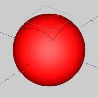
- Click OK.

- Click Cancel to exit the function.
- In the document toolbar, click
 to enter into selection mode.
 - Select the sphere.

- Delete the sphere.

Note: If the surface being projected to has two sides, meaning that it passes twice directly underneath the curves to be projected, the curved will project onto both sides just as in this example. If it passes 3 or more times, the curves will project onto the surface as many times as it passes underneath. Normally only one projection is necessary, so if more are generated then the extra projections should be deleted from the drawing.