 Spiral (Helix)
Introduction
This topic will explain where to find the Spiral function, and explain the options found in it. This topic will also give a brief description of Dynamic Drawing, the Snap Increment function, explain creation with quick steps and examples, and provide links to related topics.
The Spiral Function
The Spiral function creates a spiral or a helix based on the settings that you define in the Data Entry Manager.
Dynamic Drawing
This function supports Dynamic Drawing which allows you to use a combination of sketching and data entry to create the entities. After initially sketching the entity, it becomes an active entity, which is an entity that is in Modify Mode. Entities in Modify Mode display in the current Entity color, but displays with a greater line thickness to make them easier to identify. Active entities can be modified using data entry. The benefit of Dynamic Drawing is that you can quickly sketch a point to get the approximate result and then use data entry to update to the exact dimensions, and coordinate values as needed.
|
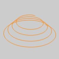
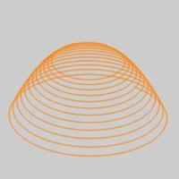
Entities in Modify Mode |
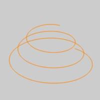
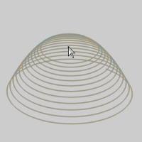
Final Entities |
|
|
In the images above, we see entities which are still in Modify Mode, followed by those same entities after they are finalized.
Snap Increment
This function support the use of the snap increment when selecting the location of the entities. The snap increment allows you to get precise results when using mouse selection and helps to reduce data entry modifications.
To learn more, view Snap Increment.
Navigation
To open Spiral:
-
In the Shapes group, of the Create 2D ribbon, click
 Spiral.
The parameters display in the Data Entry Manager.
The Data Entry Parameters
Parameters
The available parameters vary depending on whether or not the 3D Spiral option is selected. Below, the parameters have been divided into 2 columns to illustrate this.
|
Parameters
|
Parameters
|
||||
|
Output Parameters
Origin
|
|||||
- OK - finalizes the function.
- Cancel - exits the function.
Quick Steps - Spiral
Dynamic Drawing Method
-
Open the function and click a snap point or anywhere
in the graphics area to set the origin of the spiral.

You can modify the snap increment value or turn it off when selecting the origin location using the mouse.
This is now the active entity, which means the values can still be updated. -
Dynamic Drawing allows you to update the Data Entry
parameters to modify the active ellipse.
After updating the Data Entry parameters, to finish the active entity, you can click OK or start sketching the next ellipse.
When you don't need to update the Data Entry parameters, you can just click to start the next ellipse.
Tip: There are many ways to finish the active entity: click OK, press Spacebar, or click in the graphics area to start the next spiral.
-
Repeat this process for all ellipses that you want to create.
- To close the function, click Cancel.
Data Entry Method
You can also create spirals using only data entry.
-
Open the function and define all Data Entry
parameters needed for the first spiral.
-
Click OK
to create the spiral.
-
Update the Data Entry parameters, and click
OK to create the next spiral.
-
Repeat this process for as many spirals
as needed.
- To close the function, click Cancel.
Example 1 (Helix)
- In the Quick Access Toolbar, click
 New.
New. - Click anywhere in the graphics area to give it key focus, and
press Ctrl+7 to select the
ISO 2 view.
- In the Shapes group, of the Create 2D ribbon,
click Spiral.
The Spiral parameters display in the Data Entry Manager, and the preview displays the result of using the default settings.
- In the Start Radius box,
type 1.250.

- In the End Radius box,
type 3.125.
- In the Z Depth
box, leave the default value of 2.000.
- In the
Pitch box, type 0.500.
- The rest of the values will be left at default.
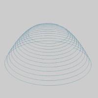
Click OK to create the spiral as shown in the CAD preview.
- To end the function, click
Cancel.
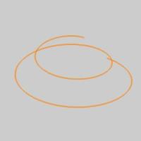
Example 2 (Helix using Variable Pitch)
- In the Quick Access Toolbar, click New.
- Click anywhere in the graphics area to give it key focus, and
press Ctrl+7 to select the
ISO 2 view.
- In the Shapes group, of the Create 2D ribbon,
click Spiral.
The Spiral parameters display in the Data Entry Manager, and the preview displays the result of using the default settings.
- In the Start Radius box,
type 1.500.

- In the End Radius box,
type 3.500.

- In the Z Depth
box, change the value to 3.000.
- In the
Pitch box, type 0.125.
- Click the Ending Pitch button to allow for a different Ending Pitch.
The preview updates to show the default of 0.000 Ending Pitch.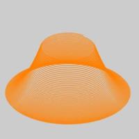
- Update the Ending Pitch value to 0.375.
- In the Output Parameters group, change the Output As option to Arcs.
- The rest of the values will be left at default.
- Move your mouse into the graphics area.
Notice the spiral follows your mouse.
- Click to place the spiral.
The spiral is in modify mode, which allows you to update any parameter, including the origin. - Click OK
to create the spiral.
- To end the function, click
Cancel.
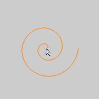
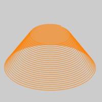
Example 3 (Spiral)
- In the Quick Access Toolbar, click New.
- Click anywhere in the graphics area to give it key focus, and
press Ctrl+7 to select the
ISO 2 view.
- In the Shapes group, of the Create 2D ribbon,
click Spiral.
The Spiral parameters display in the Data Entry Manager, and the preview displays the result of using the default settings. - In the Start Radius box,
type 0.100.

- In the End Radius box,
type 3.500.

- Deselect the 3D Spiral option at the top left of the parameters.

- Set the Number of Turns to 12.000.
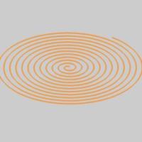
- Click OK.

- Click Cancel.

That concludes this example.