 The Shape Library
Introduction
This topic will explain the Shape Library functions, will explain where to find the functions, and explain the options found in them. This topic will also give a brief description of Dynamic Drawing, the Snap Increment function, explain creation with quick steps, and provide links to related topics.
The Shape Library Functions
Dynamic Drawing
This function supports Dynamic Drawing which allows you to use a combination of sketching and data entry to create the entities. After initially sketching the entity, it becomes an active entity, which is an entity that is in Modify Mode. Entities in Modify Mode display in the current Entity color, but displays with a greater line thickness to make them easier to identify. Active entities can be modified using data entry. The benefit of Dynamic Drawing is that you can quickly sketch a point to get the approximate result and then use data entry to update to the exact dimensions, and coordinate values as needed.
|
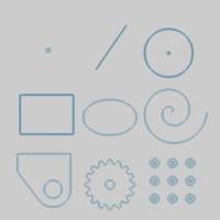
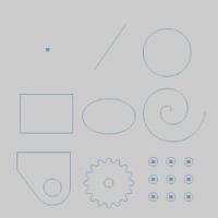
Entities in Modify Mode |
Final Entities |
|
|
In the images above, we see entities which are still in Modify Mode, followed by those same entities after they are finalized.
Snap Increment
This function support the use of the snap increment when selecting the location of the entities. The snap increment allows you to get precise results when using mouse selection and helps to reduce data entry modifications.
To learn more, view Snap Increment.
Navigation
To open the Shape Library:
- In the Shapes group, of the Create 2D ribbon, click
the Shape Library icon.
The Data Entry Parameters
The Shape Library dialog in the Data Entry Manager displays the parameters for one shape at a time. To choose a different shape, click on the diagram of the shape, and the choices will appear as shown in the image below.

Click the shape that you want to create and appropriate parameters display in the Data Entry Manager.
Shape Library Parameters
To learn about all shapes and their parameters, view Shape Library Parameters.
Parameters
Dimensions
The available dimensions vary greatly from shape to shape. Each shape will define the various size options by showing the corresponding numbers in its diagram .
Others
All of the Shape Library functions contain the Position and Orientation parameters as explained next. When creating shapes, it is often easiest to first define the parameters to get the proper shape before trying to move, mirror, or rotate the shape as explained in this section.
Note: When the Flip options are used, the shapw is flipped around the origin. Refer to the table below to see how the part behaves when flipping X, and Y, while using a bottom left origin option.
|
Bottom Left Origin and the Flip X, and Flip Y options |
||
|
|
|
|
|
Flip
X |
|
Flip X |
|
|
|
|
|
|
|
|
|
Flip
X
|
|
Flip X |
|
|
|
|


-
 - With this option selected the shape will be mirrored across the
X-axis (XZ plane) at the origin of the shape.
- With this option selected the shape will be mirrored across the
X-axis (XZ plane) at the origin of the shape. - Flip Y
- With this option selected the shape will be mirrored across the
Y-axis (YZ plane) at the origin of the shape.
- Rotation Angle - is the amount of rotation in degrees around the Z-axis at the origin of the shape.
Origin
The origin allows you to define the location of the shape based on the origin point.
- X - is the X-axis location of the origin (or reference location) of the shape.
- Y - is the Y-axis location of the origin (or reference location) of the shape.
- Z - is the Z-axis location of the origin (or reference location) of the shape.
Choose the initial Origin location on the part:
Center
Bottom Left
Bottom Center
Bottom Right
Right Center
Top Left
Top Center
Top Right
Left Center
View a Position and Orientation Example.
Quick Steps - Shape Library
-
After opening the Shape
Library, the parameters for the shape display in the Data Entry Manager and
the CAD preview shows the default shape in the graphics area.
In the Data Entry Manager, click the icon of the existing shape to view possible shapes. -
Select the shape you want to create.
-
Type all Dimension
values to define the dimensions of the shape.
The CAD preview of the shape updates in the graphics area.
Note: When defining the parameters for any shape, the CAD preview is removed when invalid values are entered. If you have entered all values for the shape and the CAD preview isn't visible, confirm you have properly defined all the parameters as shown in the Data Entry Manager diagram.
-
Modify the values in the Others
section of the Parameters
group as needed to define the parts orientation.
-
Set the location of the part by:
- Data Entry : Enter values for X, Y, and Z into the Origin group.
- Sketch : Move your mouse into the graphics area and set the shape by clicking on a snap point, or empty space. Keep in mind, the first click in the graphics area will not finalize the part. Clicking a second location however, will finalize the first.
- Combination: Use the Sketch method, and then adjust the values in the Origin group manually.
Notice the order of the two previous steps,
it is often easiest to define the shape dimensions and orientation first,
and then set the position.
- In the Data Entry Manager, click OK to create the shape as shown in the CAD preview.
(You can click Cancel to exit the function and not create the shape.)
Note: Shape Library entities are added to the CAD Tree which allows you to modify the parameters of the shapes after creating them.