 Point
Point
Introduction
This topic will explain the Point function, and the options found in it. This topic will also give brief description of Dynamic Drawing, the Snap Increment function, and will describe where to find the function, provide quick steps, and an example on how to use it, and provide links to related topics.
The Point Function
The Point function is used to create points in the graphics area. Using this creation option, points can be created by using the screen position of the mouse pointer in empty space, with or without the snap increment option, construction lines originating from applicable geometry, or snap points on existing geometry. A preview will be visible before the point is placed. The placed point will remain active, allowing data entry adjustments, until a new point is placed, OK is selected, or the function is canceled.
Tip: Although Point Sketch uses the Active UCS, you can also change the View to create points on the current viewing plane instead of the Active UCS. Just select any 2D (non-ISO) view, such as Front, Left, or Right, and click to create the points on that plane without changing the Active UCS.
Dynamic Drawing
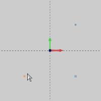
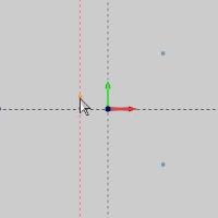
This function supports Dynamic Drawing which allows you to use a combination of sketching and data entry to create the entities. After initially sketching the entity, it becomes an active entity, which is an entity that is in Modify Mode. Entities in Modify Mode display in the current Entity color, but displays with a greater line thickness to make them easier to identify. Active entities can be modified using data entry. The benefit of Dynamic Drawing is that you can quickly sketch a point to get the approximate result and then use data entry to update to the exact dimensions, and coordinate values as needed.
|
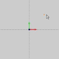
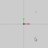
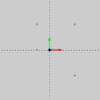
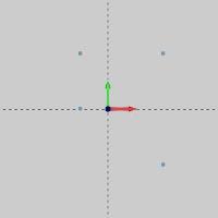
Entities in Modify Mode |
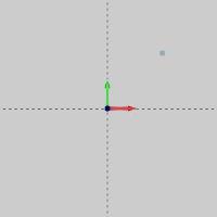
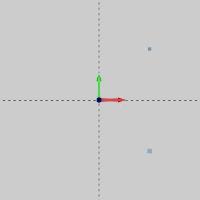
Final Entities |

|
|
In the images above, we see entities which are still in Modify Mode, followed by those same entities after they are finalized.
Snap Increment
This function support the use of the snap increment when selecting the location of the entities. The snap increment allows you to get precise results when using mouse selection and helps to reduce data entry modifications.
To learn more, view Snap Increment.
Navigation
To open Point:
-
In the Entity group of the Create 2D ribbon, click
 Point.
The parameters display in the Data Entry Manager.
Note: Whether you click the main icon, or the down arrow to get to the other options, you will have access to the same options in the Data Entry Manager.
The Data Entry Parameters
Coordinate
The Coordinate section can be used to enter the location of the point. Another method of placement, is the sketch method. By placing your mouse in the graphics area and clicking, either blank space, or a snap point, you can create an active point. The active point is not finalized until OK is selected from the Data Entry Manager, or until a new point is sketched. While the point is still in its active state, the coordinates of the point can be adjusted to fine tune its placement.
- X - sets the location along the X axis.
- Y - sets the location along the Y axis.
- Z - sets the location along the Z axis.
- OK - finalizes the function.
- Cancel - exits the function.
Point - Quick Steps
-
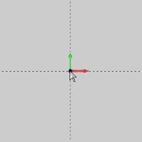
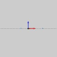
To perform the function, move your mouse into the graphics area.
There is a Preview of your point.
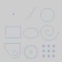
In the image below, each possible point style option is shown as a preview.
-
Click anywhere in the graphics area to create the point.
This can be accomplished using the mouse position alone, or by utilizing the snap increment option and mouse position. Construction lines and snap points can also be utilized.
This is the Sketch aspect of the function.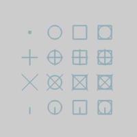
With the point placed, it remains Active, as seen above. At this time, the point has been created, but its position can still be adjusted with data entry. -
The current position of the point is reflected in the Coordinate group values.
Alter these values as needed.
Tip: All data entry boxes can also be used as a calculator. As an example, adding "-.25" to the end of the existing value, and tabbing out of the box, will subtract 0.25 from the currently listed value.
-
To finalize the active point, either:
-
Click a new point in the graphics area.
-
Click OK.
- Click Cancel.

-
Continue this process to create the needed points.
-
To close the function, click Cancel.
Example
Part 1) Sketching
- In the Quick Access Toolbar, click
 New.
New. - In the Entity group, of the Create 2D ribbon, click Point.
The Point parameters display in the Data Entry Manager. - At the bottom right of the user interface, ensure the
 snap increment toggle is turned on, and adjust the value to 0.2500.
 - At the bottom right of the user interface, ensure the
 construction geometry toggle is turned off.
 - In the graphics area, point to the center of the screen and move your mouse diagonally in the X positive, Y positive direction, until you see the preview appear in two different locations.
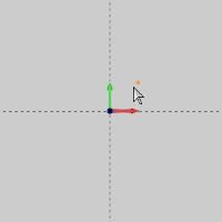
Since we are using a snap increment, we know the first location to be X 0.25, Y 0.25, and the second location to be X 0.50, Y 0.50. - Click to create a point.
This point is currently in modify mode, meaning it's location can be adjusted by adjusting the coordinates in the Data Entry Manager. - Move your mouse down into the +X, -Y quadrant until you get to X 0.50, Y-0.50.
- Click to set the point position.
Notice the previous point is no longer in modify mode.
Part 2) Modifying an Active Entity
- Move your mouse to the X -0.50, Y-0.50 position.
Click to set the point position.
- In the Data Entry Manager, adjust the Y value to Y 0.00.

- Adjust the X value to X -0.25.

- Click OK.

The point is no longer in modify mode.
Part 3) Construction Geometry
- In the bottom right of the user interface, click to turn off the snap increment. When snap increment is off, the value will be grayed out.
- Attempt to move the mouse to the Y 0.50, X -0.25 position.

Notice without the snap increment function, we cannot be sure we are in the correct location. - At the bottom right of the user interface click construction geometry to turn it on.
- Hover over the last point, as seen in the image below.

- Move your mouse up, along the vertical line, toward the first point we created.

Notice once we are horizontal to the original point, other construction geometry appears. - Click to set the point.
- Click OK to finalize the point.
Part 4) Utilizing Another UCS
-
To change to the Front view, press Ctrl+2.
Notice that all of the points are created on the current UCS (user coordinate system), or drawing plane, which is the Top (X/Y) UCS. -
Next we change the active drawing plane (UCS).
Click the UCS tab. - Click the UCS name Front (X/Z) to set it as the active layer. The active layer
always displays the green check mark (
 ) next to
the UCS name.
) next to
the UCS name.
To confirm that you are still in the Front view, press Ctrl+2. -
Next, we change the active drawing color to make it easier to view the points on different planes.
In the lower-right corner of the user interface, click the color selector arrow ( ).
).
Click to select any color box that is not the current color. Geometry is created using the active drawing color. -
In the graphics area, click to create a point in each quadrant of the front plane.


To select the ISO 2 view, press Ctrl+7.
Notice once again that the points are created using the active UCS (this time, the front plane).
Rotate the view (drag with the middle mouse button or click View, Rotate) so that you can see how each set of points is created on the active UCS plane.
To return to the default Top UCS, in the UCS tab, set the Top (X/Y) UCS to active (). -
To end the function, click Cancel.
Part 5) Utilizing Existing Geometry
-
In the Shapes group, of the Create 2D ribbon, click
 Rectangle.
The Rectangle parameters display in the Data Entry Manager. -
Below Corner Type, click
 Radius.
Leave the default Radius value 0.250.
The CAD preview updates to reflect the changes.
- Click OK.

The square is created. - Hover over the top line, without highlighting a snap point, as seen in the image below.
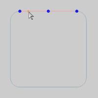
Click to create the point.
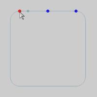
- Hover over the line to show the snap points again, and select the snap point on the left.

- Hover over the arc on the right to view the snap points.
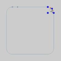
Move to the arc center snap point, and select it.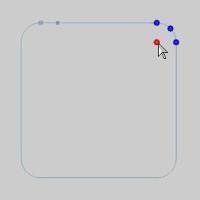

- Click OK to finalize the point.

This concludes the example.