 Extrude Boss
Introduction
This topic will explain the Extrude Boss function, will explain where to find the function, and explain the options found in it. This topic will also give a brief description of Dynamic Drawing, the Snap Increment function, explain creation with quick steps and an example, and provide links to related topics.
The Extrude Boss Function
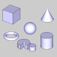
The Extrude Boss function creates solid bodies by extruding closed wireframe chains or planar surface geometry and automatically joins the intersecting (touching) entities into a single solid. When using a surface, the software automatically extracts the edges of the surface to use for the boss.
Important: Extrude
Boss automatically merges all intersecting solids into a single solid
body, unless they are hidden using the ![]() Blank function in the document toolbar. Hiding
a layer does not exclude the entities on that layer from being merged
by Extrude Boss. To extrude geometry that does not automatically merge
with other solid bodies, use Extrude Curve or Extrude Surface.
Blank function in the document toolbar. Hiding
a layer does not exclude the entities on that layer from being merged
by Extrude Boss. To extrude geometry that does not automatically merge
with other solid bodies, use Extrude Curve or Extrude Surface.
Dynamic Drawing
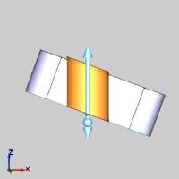
This function supports Dynamic Drawing which allows you to use a combination of sketching and data entry to create the entities. Prior to confirming the desired result in the function, an adjustable preview is visible. These previews can be modified using the sketch handles, data entry, or a combination of both. The benefit of Dynamic Drawing is that you can quickly place and adjust the size to get the approximate result, and then use data entry to update to the exact dimensions, and coordinate values as needed.
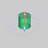
|
Preview with Sketch Handles |
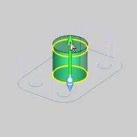
Final Entities |

|
|
In the images above, we see the preview of entities which can be adjust with sketch handles, followed by those same entities after they are finalized.
Snap Increment
This function support the use of the snap increment when selecting the location of the entities. The snap increment allows you to get precise results when using mouse selection and helps to reduce data entry modifications.
To learn more, view Snap Increment.
Navigation
To open Extrude Boss:
- In the Extrude group, of the Create 3D ribbon, click
 Extrude Boss.
The parameters display in the Data Entry Manager.
The Data Entry Parameters
Selected Geometry
|
|
|
| The list box will list the entities currently selected for the function. | |
 (Delete All)
- removes all entities from the list.
(Delete All)
- removes all entities from the list.
Positive Direction
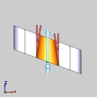
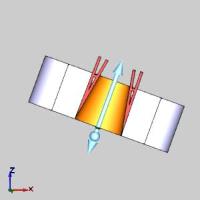
- Distance - sets the distance of the extrusion from the selected geometry in the positive direction. You can use dynamic sketch handles or data entry to set this value. The snap increment applies to the distance value when using sketch handles.
|
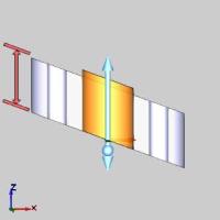
Distance Along Z-Axis |
Distance Along Normal |
|
|
-
Draft Angle - creates an angle along the edge of the extruded shape in the positive direction. This also applies to any internal shapes when you select more than one curve to extrude. This can be a positive or negative value.
Draft Along Z-Axis
Draft Along Normal
Other Direction
- Distance - sets the distance
of the extrusion from the selected geometry in the negative direction.
You can use dynamic sketch handles or data entry to set this value.
The snap increment applies
to the distance value when using sketch handles.
-
Draft Angle - creates an angle along the edge of the extruded shape in the negative direction. This also applies to any internal shapes when you select more than one curve to extrude. This can be a positive or negative value.
Options
-
 Along
Normal - the extrusion occurs parallel to the normal direction
of the plane created by the selected curve.
Along
Normal - the extrusion occurs parallel to the normal direction
of the plane created by the selected curve.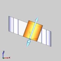
Front View 
Top View
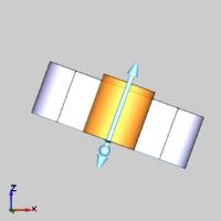
-
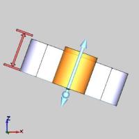
 Along
Z-Axis - the extrusion direction is the Z-axis regardless of
how the selected curve is oriented.
Along
Z-Axis - the extrusion direction is the Z-axis regardless of
how the selected curve is oriented. 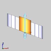
Front View 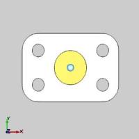
Top View
- OK - finalizes the function.
- Cancel - exits the function.
Quick Steps - Extrude Boss
|
Start |
|
Finish |

|

|
-
Open the function and define all Data Entry parameters.
-
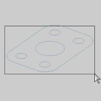
Select geometry in the graphics area.
This can sometimes be made easier by pressing S to turn off the shaded view, as seen below.
The geometry can be closed wireframe chains, surface edges, or planar surface geometry. When using a surface, the software automatically extracts the edges of the surface to use for the boss.
With geometry selected, the preview appears.
-
Use the dynamic sketch handles, with or without snap increment, and/or data entry to update the CAD preview as needed.
-
In the Data Entry tab, click OK to create the entity.
The feature is added to the CAD Tree. -
Click Cancel to close the function.
Example
A BobCAD file installed with the software can be opened to follow along with this example. This example will have you:
- Open the Example File
- Open Extrude Boss
- Create the First Extrude Boss
- Create the Second Extrude Boss
- Create the Third Extrude Boss
- Understanding and Verifying the Result
- Modifying CAD Features
Part 1) Open the Example File
-
In the Quick Access Toolbar, click
 Open.
Open. -
Navigate to: C:\BobCAD-CAM Data\BobCAD-CAM V**\Examples, and select Extrude Boss Example.bbcd.
-
With Extrude Boss Example.bbcd displaying in the File Name box, click Open.
Part 2) Open Extrude Boss
To open Extrude Boss:
- In the Extrude group, of the Create 3D ribbon, click
Extrude Boss.
The parameters display in the Data Entry Manager.
Part 3) Create the First Extrude Boss
For the first Extrude Boss, we use data entry only.
Tip: For the creation of the initial solid, you could also use Extrude Curve and get the same result. The Extrude Boss will combine any intersecting solid or surface, even if that intersecting solid or surface is on a hidden layer.
-
In the Data Entry Manager under Positive Direction, double-click in the Distance box to select all the text.
Type 0.625 to update the Distance value. -
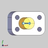
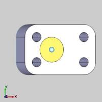
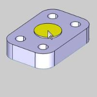
In the graphics area, click and drag a window to select the wireframe flange shape.
The entities go into the Selected Geometry list and the Preview appears.
-
In the Selected Geometry list, highlight Arc-10.
The arc highlights in the graphics area.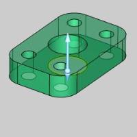
-
With Arc-10 highlighted in the Selected Geometry list, click
 (Delete).
The arc is removed from the Extrude Boss Preview.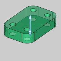
Note: The center circle is removed because it is used later to create another boss. The other four circles are selected because we want them to create the holes for the flange. By including these in the first extrude, we eliminate the need to cut the holes using another CAD function.
-
To confirm the selection, click
 (OK).
(OK).
The Extrude Boss is created in the graphics area and an Extrude
Boss feature is created in the
Extrude
Boss feature is created in the  CAD
Tree.
CAD
Tree.
That is all that is needed to create an Extrude Boss feature.
Leave the Extrude Boss function open. Another boss is created in the next part of this example.
Important
Before moving on with the example, there are a few important notes about Extrude Boss.
-
Do not delete the input (wireframe) geometry after using it to create a solid. The wireframe geometry must remain in the file, because if you delete it, the CAD feature will fail when the CAD Tree is rebuilt. This applies to any solid created from wireframe geometry, not just Extrude Boss.
Tip: You may want to keep all wireframe geometry on a separate CAD layer so that you can hide and show it as needed. (This is done in the example file using one layer named Wireframe and another layer named Solid.) To learn more about using layers, view The Layers Manager.
-
The Extrude Boss function merges all intersecting solid bodies in the file into a single solid.
Tip: You can
exclude solids from being merged by Extrude Boss using the ![]() Blank
function, found in the document toolbar, to hide the solids you don't want to merge. If the CAD Tree is
rebuilt it must, again, be Blanked, as if it is not, it will be merged
with the Boss when the CAD Tree is rebuilt. In this cases like these,
it may be better to use the Extrude Curve function in the Extrude group, of the Create 3D ribbon.
The Extrude Curve creates solids as well, but it doesn't merge solid
bodies.
Blank
function, found in the document toolbar, to hide the solids you don't want to merge. If the CAD Tree is
rebuilt it must, again, be Blanked, as if it is not, it will be merged
with the Boss when the CAD Tree is rebuilt. In this cases like these,
it may be better to use the Extrude Curve function in the Extrude group, of the Create 3D ribbon.
The Extrude Curve creates solids as well, but it doesn't merge solid
bodies.
Part 4) Create the Second Extrude Boss
For the second Extrude Boss, we explore Dynamic Drawing.
-
Under Positive Direction, click in the right side of the Distance box so the cursor displays after the current value of 0.625.
-
Type +0.05 and press Tab to update the value.
The value displays 0.675. -
To make it easier to select the geometry press S, or in the document toolbar, click
 Shaded.
The Shading disappears.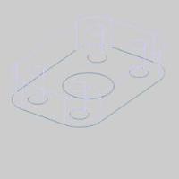
-
Hover over the center arc as shown in the image below.

-
The CAD preview displays.

-
Under the graphics area, change the value of the
 (Snap
Increment) to 0.2500.
(Snap
Increment) to 0.2500.
This allows us to sketch CAD sizes and depths in increments of 0.2500. -
Now to show how to use the dynamic sketch handles.
Hover over the lower sketch handle to highlight it.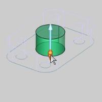
-
Click to select the lower sketch handle.
The sketch handle highlights and shows the next possible position based on our Snap Increment.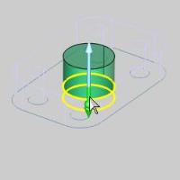
-
Move the sketch handle down slightly.
The Preview displays the next possible position based on our Snap Increment.
-
Move the sketch handle back to the 0.2500 position and click to set it to create a small extrusion on the underside of the part.
The Preview updates to show the current Other Direction amount.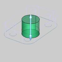
-
To confirm the selection, click
(OK).
The Extrude Boss is created in the graphics area and anotherExtrude
Boss feature is created in the CAD
Tree.
-
Pres S, or select
Shaded from the
document toolbar. 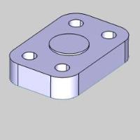
Leave the Extrude Boss function open. Another
boss is created in the next part of this example.
Part 5) Create the Third Extrude Boss
-
Hover over the center extrusion as seen in the image below.
-
Click the highlighted surface.
The Preview displays.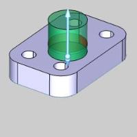
-
In the Positive Direction group, change the Distance to 0.2500.
The Preview updates.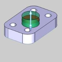
-
In the Draft Angle box, type 45.00, and press Tab.
Note: The Draft Angle can be a positive or negative value.
The Preview updates.
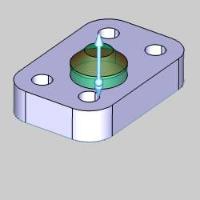
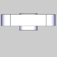
Note: As you can see here, we are extruding in two different direction using a different draft angle on top. Although the Other Direction of the extrusion is the value we used for the second extrusion, this will not affect our current extrusion, and therefore, does not have to be changed.
-
To finish the third extrude, click OK in the Data Entry Manager.
The Extrude Boss is created in the graphics area a thirdExtrude
Boss feature is created in the CAD
Tree.
-
To close the Data Entry Manager, click Cancel.
Part 5) Understanding and Verifying the Result
It is important to understand that the Extrude Boss function merges all intersecting solid bodies into a single solid body. The CAD Tree helps to illustrate this fact. When you close the Data Entry Manager, the CAD Tree Manager automatically displays.
-
Notice that there are three Extrude Boss features in the CAD Tree.
The CAD Tree provides many tools to help you modify, verify, and organize your CAD features.
If you enable selection mode and point to the solid in the graphics area, you can see that it highlights as a single solid body.
Another way to confirm this is to use the Solids folder in the CAD Tree. -
Double-click the
 Solids folder to expand it, or,
click the small
Solids folder to expand it, or,
click the small  plus sign.
Notice that there is one item, Solid 1.
Click Solid 1 to highlight the solid body in the graphics area.
All of the feature items in the CAD Tree show a preview when you click them. -
Click the first Extrude Boss feature in the CAD Tree, and notice the result of the feature is highlighted in the graphics area.
To make this easier to view, in the Layers Manager, right-click Solid and click Hide.
Note: Notice that there are no longer any items in the Solids folder of the CAD Tree. The Solids folder only contains Solid items that are currently visible in the graphics area. Hiding the Solid layer temporarily removes the Solid item from the Solids folder.
-
Click each feature and geometry item in the CAD Tree to view the result or selection of the feature, respectively. Expand each feature if needed.


-
In addition to the highlighting of CAD feature results and geometry selection, the CAD Tree also provides modification tools as explained in the next part of this example.
-
In the Layer Manager, right-click Solid and click Show.
Part 6) Modifying CAD Features
The CAD Tree Manager allows you to modify the parameters and/or geometry selection of solid features that you create. Numerous ways are provided so you can use the most efficient method depending on what you need to accomplish. All of this information is explained in The CAD Tree. The following steps provide two examples.
-
Right-click
Extrude
Boss under Flange 5 Hole, and click Edit.
The Extrude Boss function opens with the CAD preview. The associated geometry is already in the Selected Geometry list. The condition of the model is the same as it was when you created the feature.
-
Under Positive Direction, change the Distance value to 0.500.
The Preview updates.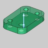
-
In the Draft Angle box, type -5.000.
The Preview updates.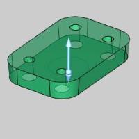
-
To finish editing the feature, click OK.
The CAD feature is automatically rebuilt with the new parameters.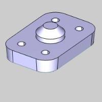
The CAD Tree provides the tools to help you easily modify CAD models to accommodate design changes.
This concludes the example. View the Extrude Cut Example to learn about cutting the hole in the center of the flange created in this example.