 Extrude Cut
Introduction
This topic will explain the Extrude Cut function, will explain where to find the function, and explain the options found in it. This topic will also give a brief description of Dynamic Drawing, the Snap Increment function, explain creation with quick steps and an example, and provide links to related topics.
The Extrude Cut Function
The Extrude Cut function removes material from solid bodies by extruding closed wireframe chains or planar surface geometry to the specified distance and subtracts the result from any intersecting solid or surface bodies. When using a surface, the software automatically extracts the edges of the surface to use for the cut.
Important: Extrude
Cut is applied to all intersecting bodies in the file, unless they are
hidden using the ![]() Blank function, in the document toolbar. Hiding a layer does not exclude
the entities on that layer from being used in Extrude Cut.
Blank function, in the document toolbar. Hiding a layer does not exclude
the entities on that layer from being used in Extrude Cut.

Dynamic Drawing
This function supports Dynamic Drawing which allows you to use a combination of sketching and data entry to create the entities. Prior to confirming the desired result in the function, an adjustable preview is visible. These previews can be modified using the sketch handles, data entry, or a combination of both. The benefit of Dynamic Drawing is that you can quickly place and adjust the size to get the approximate result, and then use data entry to update to the exact dimensions, and coordinate values as needed.
|
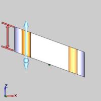
Preview with Sketch Handles |
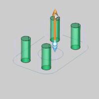
Final Entities |

|
|
In the images above, we see the preview of entities which can be adjust with sketch handles, followed by those same entities after they are finalized.
Snap Increment
This function support the use of the snap increment when selecting the location of the entities. The snap increment allows you to get precise results when using mouse selection and helps to reduce data entry modifications.
To learn more, view Snap Increment.
Navigation
To open Extrude Boss:
- In the Extrude group, of the Create 3D tab, click
 Extrude Cut.
The parameters display in the Data Entry Manager.
The Data Entry Parameters
Selected Geometry
|
|
|
| The list box will list the entities currently selected for the function. | |
 (Delete All)
- removes all entities from the list.
(Delete All)
- removes all entities from the list.
Positive Direction
- Distance - sets the distance of the extrusion from the selected geometry in the positive direction. You can use dynamic sketch handles or data entry to set this value. The snap increment applies to the distance value when using sketch handles.
|
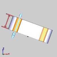
Distance Along Z-Axis |
Distance Along Normal |
|
|
-
Draft Angle - creates an angle along the edge of the extruded shape in the positive direction. This also applies to any internal shapes when you select more than one curve to extrude. This can be a positive or negative value.
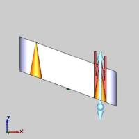
Draft Along Z-Axis
Draft Along Normal
Other Direction
- Distance - sets the distance
of the extrusion from the selected geometry in the negative direction.
You can use dynamic sketch handles or data entry to set this value.
The snap increment applies
to the distance value when using sketch handles.
-
Draft Angle - creates an angle along the edge of the extruded shape in the negative direction. This also applies to any internal shapes when you select more than one curve to extrude. This can be a positive or negative value.
Options
-
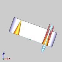
 Along
Normal - the extrusion occurs parallel to the normal direction
of the plane created by the selected curve.
Along
Normal - the extrusion occurs parallel to the normal direction
of the plane created by the selected curve.
Front View 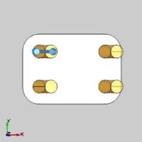
Top View
-
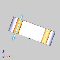
 Along
Z-Axis - the extrusion direction is the Z-axis regardless of
how the selected curve is oriented.
Along
Z-Axis - the extrusion direction is the Z-axis regardless of
how the selected curve is oriented.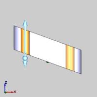

Front View 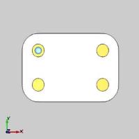
Top View
- OK - finalizes the function.
- Cancel - exits the function.
Quick Steps - Extrude Cut
|
Start |
|
Finish |

|
|
-
Open the function and define all Data Entry parameters.
-
Select geometry in the graphics area.
This can sometimes be made easier by pressing S to turn off the shaded view, as seen below.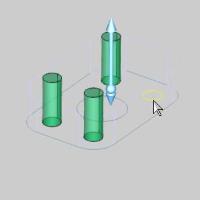
The geometry can be closed wireframe chains, surface edges, or planar surface geometry. When using a surface, the software automatically extracts the edges of the surface to use for the boss.
With geometry selected, the preview appears.
-
Use the dynamic sketch handles, with or without snap increment, and/or data entry to update the CAD preview as needed.

-
In the Data Entry Manager, click OK to create the entity.
The feature is added to the CAD Tree. -
Click Cancel to close the function.
Example
A BobCAD file installed with the software can be opened to follow along with this example.
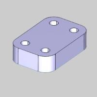
In the example file, Extrude Cut is used to cut a hole through the center of a solid flange.

Part 1) Open the Example File
-
In the Quick Access Toolbar, click
 Open.
Open. -
Navigate to: C:\BobCAD-CAM Data\BobCAD-CAM V**\Examples, and select Extrude Cut Example.bbcd.
-
With Extrude Cut Example.bbcd displaying in the File Name box, click Open.
Part 2) Open Extrude Cut
To open Extrude Cut:
- In the Extrude group, of the Create 3D tab, click Extrude Cut.
The parameters display in the Data Entry Manager.
Part 3) Create an Extruded Cut
When using Extrude Cut, you can select closed wireframe chains or planar surface geometry. For this example, we select a wireframe chain and then explore Dynamic Drawing to define the extrusion direction and distance from the chain.
-
Press S, or select
 Shaded from the document toolbar.
The Shading is removed from the model.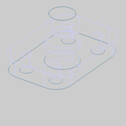
-
Under the graphics area, change the value of the
 (Snap
Increment) to 0.2500.
(Snap
Increment) to 0.2500.
This allows us to sketch CAD sizes and depths in increments of 0.2500. -
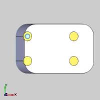
For this example, we select the geometry first before defining the Data Entry parameters. This way we can create the CAD preview and explore Dynamic Drawing.
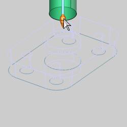
In the graphics area, hover over the circle, as seen in the image below.
-
Click the arc to add it to the Selected Geometry list.
The Preview appears.
Note: Notice that by default the circle is extruded one unit in the positive direction. For any Extrude function, you can specify the extrude distance in either or both directions from the selected geometry. You can also apply a Draft Angle to either or both directions.
-
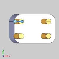
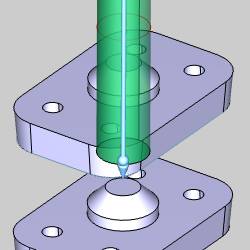
To show how Dynamic Drawing works, hover over the sketch handle as seen in the image below.
-
Click the sketch handle to activate it.
The sketch handle highlights and the preview moves down based on the next snap increment.
Note: When a sketch handle is activated, the CAD preview changes to a wireframe display until you place the sketch handle. Move the handle down and notice it does not move smoothly, but jumps by an incremental amount. This is the snap increment amount that has been set. Notice too, that the Other Direction Distance is updating as the sketch handle is being moved.
-
Move the sketch handle so that the Other Direction Distance is set to 3.0000.

-
Click to set the sketch handle.
The Preview updates.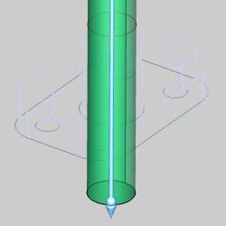
-
To perform the Extrude Cut, click OK in the Data Entry Manager.
The Extrude Boss is created in the graphics area and another Extrude
Cut feature is created in the
Extrude
Cut feature is created in the  CAD
Tree.
CAD
Tree.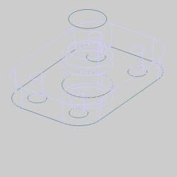
-
Press S, or select
Shaded from the document toolbar.
The Shading appears on the model.
-
To close the Data Entry Manager, click Cancel.
The process of creating an Extrude Cut is complete. The rest of this example provides some important usage tips.
Part 4) Excluding Solids from Extrude Cut
It is important to understand that any solid body in the file that intersects
the extruded shape is included in the Extrude Cut result. This applies
to all visible or hidden solids unless
they are hidden using the ![]() Blank command, found in the document toolbar. Hiding a CAD layer
does not exclude the solids on
that layer.
Blank command, found in the document toolbar. Hiding a CAD layer
does not exclude the solids on
that layer.
-
In the Layer Manager, click the Layers tab if it isn't already selected.
-
In the Layers Manager, right-click the layer name Flange Copy, and click Show.
If needed, rotate the view to see that the second flange was also cut, even though it was on a hidden CAD layer.
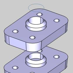
If the second flange was hidden using Blank, it would not have been included in the Extrude Cut.
Tip: After hiding a solid using Blank in order to exclude it from an Extrude Cut, or Boss and then showing the solid using Unblank, if the CAD Tree is rebuilt, that solid will then be included in the Extrude Cut result. If this creates a problem, you can use Solid Subtract instead of Extrude Cut.
For this example we didn't want to cut the second flange. This problem is easily resolved by editing the Extrude Cut feature.
Part 5) The CAD Tree
One CAD feature is added to the CAD Tree each time you perform Extrude Cut. The feature in the CAD Tree provides many tools for editing, suppressing, renaming the feature, and more as explained in the CAD Tree.
After closing the Data Entry Manager, the CAD Tree automatically displays.
You can also click the in the ![]() CAD Tree Manager to access the CAD Tree.
CAD Tree Manager to access the CAD Tree.
-
Notice the
 Extrude
Cut feature at the bottom of the CAD Tree.
Extrude
Cut feature at the bottom of the CAD Tree.
Right-click Extrude Cut, and click Edit.
The CAD preview displays, and the Extrude Cut Parameters open in the Data Entry Manager.
-
Under Other Direction, change the Distance value to 2.000, and press Tab to update the preview.
-
To finish editing the feature, click OK.
This concludes the example.