 Split Solid
Introduction
This topic will explain the Split Solid function, will explain where to find the function, and explain the options found in it. This topic will also explain creation with quick steps, and provide links to related topics.
The Split Solid Function
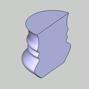
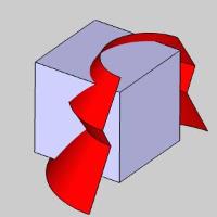
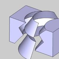
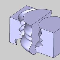
The Solid Split function is used to separate a solid body using a splitting surface. For this function, you select a single solid and a splitting surface and the software automatically creates multiple solids from the original solid body.
Important: The splitting surface must completely pass through the solid or the function can't split the solid.
Navigation
To open Split Solid:
- In the Primitives group, of the Create 3D tab, click
 Split.
The parameters display in the Data Entry Manager.
The Data Entry Parameters
Solid to Split
|
|
|
| The list box will list the entity currently selected for the function. | |
Splitting Surface
- Face Picking
 - allows you to select a solid as the split surface.
 - allows only a single face to be selected as the split surface.
|
|
|
|
|
|
|
|
|

Splitting Surface
|
|
|
| This list box will show the entity currently selected for the function. | |
- OK - finalizes the function.
- Cancel - exits the function.
Quick Steps - Split Solid
-
Open the function.
The Solid to Split list automatically has focus to allow you to select the solid to affect.
If you want to split the solid with multiple joined surfaces, use the default, Face Picking off (check box cleared).
If you want to split the solid with a single continuous surface, select the Face Picking check box to turn on the option. -
Click to select a single solid entity that you want to split.
The geometry selection is automatically confirmed and focus moves to the Splitting Surface list. -
Click to select the splitting surface or face.
-
Click OK to split the solid.
The feature is added to the CAD Tree. -
Repeat this process as needed.
-
Click Cancel to close the function.
Example
A BobCAD file installed with the software can be opened to follow along with this example. This example will have you:
- Open the Example File
- Open Split Solid
- Select Geometry to Split
Part 1) Open the Example File
-
In the Quick Access Toolbar, click
 Open.
Open. -
Navigate to: C:\BobCAD-CAM Data\BobCAD-CAM V**\Examples, and select Split Solid Example.bbcd.
-
With Split Solid Example.bbcd displaying in the File Name box, click Open.
Part 2) Open Split Solid
To open Split Solid:
- In the Primitives group, of the Create 3D tab, click
Split.
The parameters display in the Data Entry Manager.
Part 3) Select Geometry to Split
- Click to select the solid cube in the graphics
area.
Notice the cube is a single entity.
The cube is added to the Selected Geometry list and focus is shifted to the Splitting Surface list.
- Click
to select the splitting surface.
The surface is added to the Splitting Surface list.
Click OK to split the solid.
The solid is split and a Split Solid feature is created
in the
Split Solid feature is created
in the  CAD
Tree.
CAD
Tree. - In the
Layer Manager, right-click
Surface,
and click Hide.

When you point to each side of the cube, you can see that it is now two solid bodies.

- To close
the Data Entry Manager, click Cancel.
That is all that is needed to split a solid body.
This concludes the example.