 Extrude Surface
Introduction
This topic will explain the Extrude Surface function, will explain where to find the function, and explain the options found in it. This topic will also give a brief description of Dynamic Drawing, the Snap Increment function, explain creation with quick steps and an example, and provide links to related topics.
The Extrude Surface
The Extrude Surface function creates a solid or surface shell by extruding surface geometry.

Tip: This function does not merge the result with other solid bodies. To extrude a surface that merges with other solid bodies, use Extrude Boss.
Dynamic Drawing
This function supports Dynamic Drawing which allows you to use a combination of sketching and data entry to create the entities. Prior to confirming the desired result in the function, an adjustable preview is visible. These previews can be modified using the sketch handles, data entry, or a combination of both. The benefit of Dynamic Drawing is that you can quickly place and adjust the size to get the approximate result, and then use data entry to update to the exact dimensions, and coordinate values as needed.
|
Preview with Sketch Handles |
Final Entities |

|
|
In the images above, we see the preview of entities which can be adjust with sketch handles, followed by those same entities after they are finalized.
Snap Increment
This function support the use of the snap increment when selecting the location of the entities. The snap increment allows you to get precise results when using mouse selection and helps to reduce data entry modifications.
To learn more, view Snap Increment.
Navigation
To open the Extrude Surface function:
- In the Extrude group, of the Create 3D tab, click
 Extrude Surface.
The parameters display in the Data Entry Manager.
The Data Entry Parameters
Selected Geometry
|
|
|
| The list box will list the entities currently selected for the function. | |
 (Delete All)
- removes all entities from the list.
(Delete All)
- removes all entities from the list.
Positive Direction
- Distance - sets the distance of the extrusion from the selected geometry in the positive direction. You can use dynamic sketch handles or data entry to set this value. The snap increment applies to the distance value when using sketch handles.
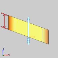
|
Distance Along Z-Axis |
Distance Along Normal |
|
|
-
Draft Angle - creates an angle along the edge of the extruded shape in the positive direction. This also applies to any internal shapes when you select more than one curve to extrude. This can be a positive or negative value.
Draft Along Z-Axis
Draft Along Normal

Other Direction
- Distance - sets the distance
of the extrusion from the selected geometry in the negative direction.
You can use dynamic sketch handles or data entry to set this value.
The snap increment applies
to the distance value when using sketch handles.
-
Draft Angle - creates an angle along the edge of the extruded shape in the negative direction. This also applies to any internal shapes when you select more than one curve to extrude. This can be a positive or negative value.
Options
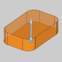
- With Caps
![]() - Extrudes the wireframe geometry and adds a surface to the top and bottom. All surfaces are stitched into a solid
- Extrudes the wireframe geometry and adds a surface to the top and bottom. All surfaces are stitched into a solid
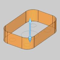
![]() - Extrudes the wireframe geometry without adding a surface to the top and bottom.
- Extrudes the wireframe geometry without adding a surface to the top and bottom.
|
|
|
|
|
|
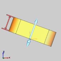
-
 Along
Normal - the extrusion occurs parallel to the normal direction
of the plane created by the selected curve.
Along
Normal - the extrusion occurs parallel to the normal direction
of the plane created by the selected curve.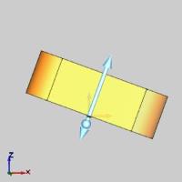
Front View 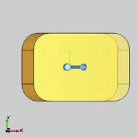
Top View
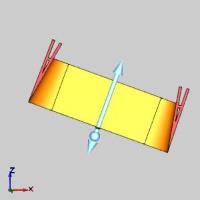
-
 Along
Z-Axis - the extrusion direction is the Z-axis regardless of
how the selected curve is oriented.
Along
Z-Axis - the extrusion direction is the Z-axis regardless of
how the selected curve is oriented.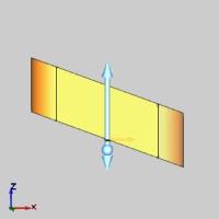
Front View 
Top View
- OK - finalizes the function.
- Cancel - exits the function.
Quick Steps - Extrude Surface
- Open the function.
The Selected Geometry list automatically has focus. - Select the surface to be extruded.
The surface is added to the Selected Geometry list.
A preview appears showing the result using the default parameters. - Update the parameters to achieve the desired result, which is visible in the preview.
- Click OK to confirm the result.
The feature is added to the CAD Tree. - Repeat the function as necessary.
Tip: Instead of applying features to solids and surfaces more than once, go to the CAD Tree to edit the existing feature. Since all solid and surface moves, and modifications are stored in the CAD Tree, editing a feature is preferable to adding many more to achieve the desired result. This will keep file size down and help ensure files don't become slow to respond.
- Click Cancel to exit the function.
Example
Note: In the images below, both the Show Axis X-Y and Show Gnomon toggles have been disabled in the Axis X-Y group of the Settings Part > Display dialog.
-
In the Quick Access Toolbar, click
 New.
New. -
In the Surfaces group, of the Create 3D ribbon, click the down arrow under
 Planar, and select
  Rectangular Plane.
The Rectangular Plane parameters display in the Data Entry Manager and the Preview appears showing the default values.
Important: The location of the Preview will vary based on the last mouse location, until the Base Point value is updated in the Data Entry Manager. However, if you click OK, the location will be placed at the Base Point, and not the preview location.
-
In the Data Entry Manager, leave the Width and Height values at their default values, but in the Corner Type group, select
 to create a fillet, and set the value to 0.6250.
The Preview updates.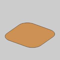
-
Click OK.
The Rectangular Plane is created in the graphics area and aRectangular
Plane feature is created in the CAD Tree. 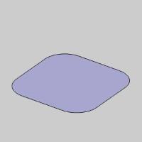
-
In the Extrude group, of the Create 3D tab, click
Extrude Surface.
The Extrude Surface parameters display in the Data Entry Manager. -
Click the Rectangular Plane in the graphics area to add it to the Selected Geometry list.
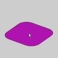
The Rectangular Plane (Face 2-0) is added to the Selected Geometry list and the Preview is updated.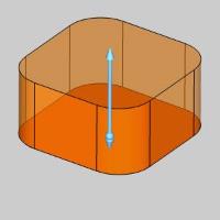
Note: The names of the geometries added to the Selected Geometry list will vary based on the amount of geometry in the file. For instance, this Rectangular Plane will always be listed as "Face ...". if it is the only geometry in the file, it will be labeled as "Face 2-0".
-
In the Positive Direction group, Input 0.5000 for the Distance.
The Preview updates.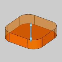
-
Click OK to confirm.
The Extrude Surface is created in the graphics area and aExtrude Surface feature is
created in the  CAD Tree.
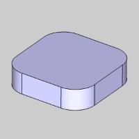
-
To end this function, click Cancel.
That concludes this example.