 Surface Fillet
Introduction
This topic will explain the Surface Fillet function, and the options found in it. This topic will also describe where to find the function, provide quick steps and an example on how to use it, and provide links to related topics.
The Surface Fillet Function
The Fillet Surfaces function is used to join two separate surfaces with a defined radius between them using one of five trimming options. To ensure tangency, this function trims surfaces, but it does not extend them.
Navigation
To open the Surface Fillet function:
- In the Corners group, of the Create 3D tab, click
 Surface Fillet.
The parameters display in the Data Entry Manager.
The Data Entry Parameters
Boundary Trim Type
The boundary options determine how the fillet is trimmed at the outer boundaries. The following image shows the two original surfaces as a reference to the result shown below each option.

-
Blend - creates the fillet by trimming it and creating a tangent blend with the surface edges.

-
No Trim - creates the fillet between the two surfaces, but does not trim the outer edges of the fillet. The resulting fillet exceeds the larger surface by the radius amount.

-
Minimal - creates the fillet using the smaller surface.

-
Maximal - creates the fillet using the larger surface.

-
Bevel - create the fillet by trimming it and creating a beveled edge between the two surfaces.

First Surface/Solid
|
|
|
| The list box will list the entity currently selected for the function. | |
Second Surface/Solid
|
|
|
| This list box will show the entity currently selected for the function. | |
Parameters
- Radius - sets the radius
value of the fillet.
- Tolerance - sets the tolerance for the creation of the surface fillet.
- OK - finalizes the function.
- Cancel - exits the function.
Quick Steps - Surface Fillet
- Open the function.
The First Surface list is automatically given focus. - Select the first surface
The surface is added to the First Surface list.
Focus is automatically placed on the Second Surface list. - Select the second surface.
The surface is added to the Second Surface list.
The preview displays showing the result with default parameters. - Update the parameters to achieve the desired result, which is visible in the preview.
- Click OK to confirm.
The feature is added to the CAD Tree. - Repeat as necessary.
- Click Cancel to confirm the function.
Example
This example will demonstrate how to use the Fillet Surface function. This example will have you:
- Open a New Window
- Adjust View
- Create a Rectangular Plane
- Move to the Front Plane
- Create Another Rectangular Plane
- Move to the Top Plane
- Selecting the Geometry
- Adjusting the Results
Note: In the images below, both the Show Axis X-Y and Show Gnomon toggles have been disabled in the Axis X-Y group of the Settings Part > Display dialog.
Part 1) Open a New Window and Adjust View
-
In the Quick Access Toolbar, click
 New.
New.
Part 2) Adjust the View
-
Enter an ISO 2 view by pressing Ctrl+7.
Part 3) Create a Rectangular Plane
-
In the Surfaces group, of the Create 3D ribbon, click the down arrow under
 Planar, and select
  Rectangular Plane.
The Rectangular Plane dialog opens in the Data Entry Manager.
The Preview appears at X0, Y0, Z0.
-
Click OK to confirm this surface.
The surface is created in the graphics area and aRectangular Plane feature is added
to the  CAD
Tree.
CAD
Tree. 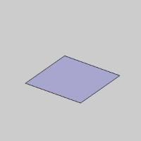
Part 4) Move to the Front Plane
-
In the UCS Manager, click Front (X/Z) in order to create another surface on the Front Plane.
The Front Plane highlights.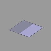
Part 5) Create Another Rectangular Plane
-
In the Rectangular Plane dialog, set the Dimensions to:
-
Width = 3.0000
-
Height = 3.0000
The Preview updates.

-
In the Base Point group, change the Z value to -1.0000.
The Preview updates.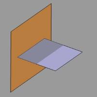
-
Click OK to confirm this surface.
The surface is created in the graphics area and anotherRectangular
Plane feature is added to the CAD
Tree. 
Part 6) Move to the Top Plane
-
In the UCS Manager, click Top (X/Y).
The Front Plane disappears.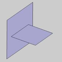
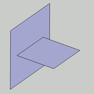
Part 7) Selecting the Geometry
-
In the Corners group, of the Create 3D tab, click
Surface Fillet.
The Fillet Surface dialog opens in the Data Entry Manager. -
Hover over the surface created on the Front Plane as shown in the image below.
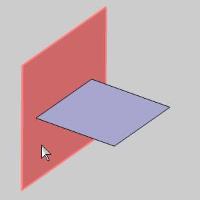
-
Select the surface.
The surface is added to the First Surface/Solid list.
-
Hover over the surface created on the Top Plane as shown in the image below.
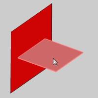
-
Select the surface.
The surface is added to the Second Surface/Solid list and the Preview appears showing the result if the default Blend option is used.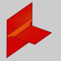
Part 8) Adjusting the Results
-
In the Boundary Trim Type group, select No Trim.
The Preview updates to show the result if the No Trim option is used.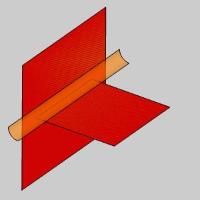
-
In the Boundary Trim Type group, select Minimal.
The Preview updates to show the result if the Minimal option is used.
-
In the Boundary Trim Type group, select Maximal.
The Preview updates to show the result if the Maximal option is used.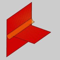
-
In the Boundary Trim Type group, select Bevel.
The Preview updates to show the result if the Bevel option is used.
-
In the Parameters group, change the Radius value to 0.5000.
The Preview updates.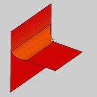
-
Click OK to finalize the Surface Fillet.
The surface fillet is created in the graphics area and anotherFillet Surface feature
is added to the CAD Tree.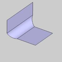
-
To end this function, click Cancel.
This concludes the example.