 Intersection Curves
Introduction
This topic will explain the Intersection Curves function, will explain where to find the function, and explain the options found in it. This topic will also explain creation with quick steps and an example, and provide links to related topics.
The Intersection Curves Function
Intersection Curves is used to extract the curves formed by the intersection of two solids or surfaces. To perform the function, you select the solids or surfaces in the graphics area. The curves are automatically created when you select the second solid/surface.

Tip: It is helpful to create a new layer and set it as the active layer before opening the function to automatically place the extracted curves on the separate layer. Otherwise, you must delete or hide the original geometry to see the curves.
Navigation
To open the Intersection Curves function:
- In the Modify group, of the Create 3D tab, click
 Intersection Curves.
The parameters display in the Data Entry Manager.
The Data Entry Parameters
The function is performed using only geometry selection.
First Surface/Solid
|
|
|
| The list box will list the entity currently selected for the function. | |
Second Surface/Solid
|
|
|
| This list box will show the entity currently selected for the function. | |
- OK - finalizes the function.
- Cancel - exits the function.
Quick Steps - Intersection Curves
- Open the function.
The First Surface/Solid list automatically has focus. - Select the first surface, or solid.
The entity is added to the Fist Surface/Solid list.
The Second Surface/Solid list is automatically given focus. - Select second surface, or solid.
The entity added to the Second Surface/Solid list.
A preview of the intersection of curves appears. - Click OK to confirm.
- Repeat as necessary.
- Click Cancel to exit the function.
Example
This example will demonstrate how to use the Fillet Surface function.
Note: In the images below, both the Show Axis X-Y and Show Gnomon toggles have been disabled in the Axis X-Y group of the Settings Part > Display dialog.
-
In the Quick Access Toolbar, click
 New.
New. -
Enter an ISO 2 view by pressing Ctrl+7.
-
In the Primitives group, of the Create 3D tab, click
 Cube.
Cube.
The Cube dialog opens in the Data Entry Manager.
The Preview appears.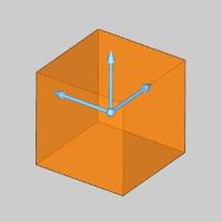
-
Click OK to create the Cube.
The Cube is created in the graphics area and aCube feature is added to the
 CAD
Tree.
CAD
Tree. 
-
In the Primitives group, of the Create 3D tab, click
 Sphere.
The Cube dialog opens in the Data Entry Manager.
The Preview appears.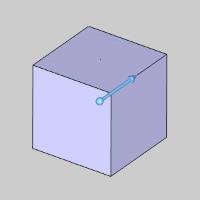
-
Change the Radius value to 1.5000.
The Preview updates.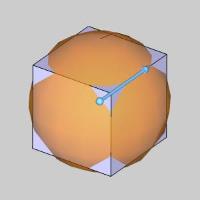
-
Click OK to create the Sphere.
The Sphere is created in the graphics area and aSphere feature is added to the CAD
Tree.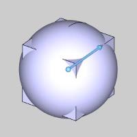
-
In the LayersManager, right-click and select Add New Layer.
A new layer is created and automatically set as the active layer. Upon creation the name is highlighted to allow you to rename. -
Name the new layer Intersection and press Enter.
The layer is renamed. -
In the Modify group, of the Create 3D tab, click
Intersection Curves.
The Intersection Curves dialog opens in the Data Entry Manager.
The First Surface/Solid list has focus by default to allow you to add a surface or solid upon opening the function. -
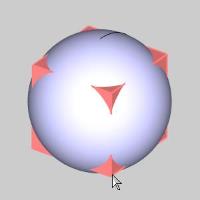
Hover over the Cube as seen in the image below.
-
Click to select the Cube.
The Cube is selected and is added to the First Surface/Solid list.
Focus is shifted to the Second Surface/Solid list.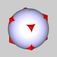
-
Hover over the Sphere as seen in the image below.
-
Click to select the Sphere.
The Sphere is selected and is added to the Second Surface/Solid list.
The Preview appears.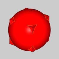
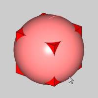
Note: At the point, the Preview is visible, but may be difficult to see depending on the Selection and Highlight colors being used.
-
Press S to toggle the Shaded view, or click
 Shaded from
the Document Toolbar.
Shaded from
the Document Toolbar.
The shading is removed from the model.
-
Click OK to confirm the Intersection Curves.
The Intersection Curves are created.
-
Right-click the CAD layer in the Layers Manager and select Hide, in order to hide the Cube and Sphere from view.

-
Click Cancel to close the function.
This concludes the example.