 Multisided Patch
Introduction
This topic will explain the Multisided Patch function, will explain where to find the function, and explain the options found in it. This topic will also explain creation with quick steps and examples, and provide links to related topics.
The Multisided Patch Function
The Multisided Patch function is used to create a 3-dimensional surface from a closed chain that consists of 3 or more edge curves. To perform the function, you chain select each geometry curve one at a time in a consecutive order. After the chain direction of all edge curves is defined, you confirm the selection to create the surface.
Navigation
To open Multisided Patch:
- In the Surfaces group, of the Create 3D tab, click
 Multisided Patch.
The parameters display in the Data Entry Manager.
The Data Entry Parameters
-
 Preview - Select the check box to enable the CAD preview, which displays what the result will be before you create it. Once all geometry is selected, the preview is shown.
  Preview - Clear the check box
to turn off the CAD preview.
Preview - Clear the check box
to turn off the CAD preview.
Selected Geometry
|
|
|
| The list box will list the entities currently selected for the function. | |
|---|---|
 (Delete All)
- removes all entities from the list.
(Delete All)
- removes all entities from the list.
- OK - finalizes the function.
- Cancel - exits the function.
Quick Steps - Multisided Patch
When creating a Multisided Patch, you complete one chain selection for each side of the surface. Each chain can be one or more entities. The selection order determines the results, and the chains should all share the same general direction, such as clockwise.
- Open the function.
The Selected Geometry list automatically has focus. - Chain select the first chain.
- Chain select the remaining chains.
Once surface creation is possible, a preview will appear. - Use the controls next to the Selected Geometry list to adjust the direction of chains, the chains order in the list, and which chains are in the list.
- Click OK to create the surface.
The feature is added to the CAD Tree. - Repeat as necessary.
- Click Cancel to exit the function.
Example 1
This example will demonstrate how to use the Multisided Patch function.
Note: In the images below, both the Show Axis X-Y and Show Gnomon toggles have been disabled in the Axis X-Y group of the Settings Part > Display dialog.
-
In the Quick Access Toolbar, click
 Open.
Open. -
In the Open dialog box, navigate to C:\BobCAD-CAM Data\BobCAD-CAM V**\Examples.
Note: This is the default install location. If you performed a custom install, navigate to the location in which you installed the software.
-
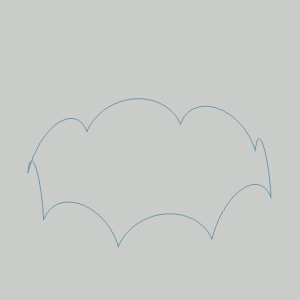
Select multisided patch surface example.bbcd, and click Open.
The file opens.
Leave the file in the ISO 2 view. -
In the Surfaces group, of the Create 3D tab, click
Multisided Patch.
The Multisided Patch parameters display in the Data Entry Manager. -
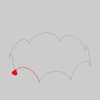
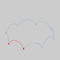
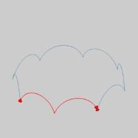
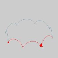
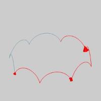
Highlight the end of the first entity, of the first chain, as seen in the image below.
Note: In this example, each chain is a single entity. If these chains were multiple entities, the steps would be the same; Click the end of the first entity of the first chain to set the start point and direction of the chain. Then hold Shift and click the end of the last entity of the first chain to set the end of the chain. Then repeat for the second and third chains.

-
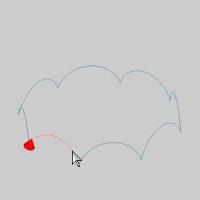
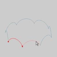
Click the entity to set the start of the chain.
-
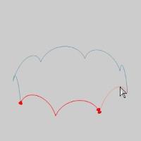
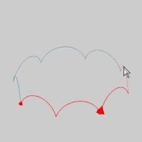
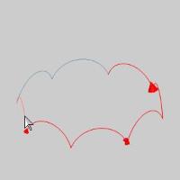
Highlight the end of the first chain as seen in the image below.
-
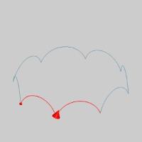
Press and hold Shift on the end of the entity to set the end of the chain.
The chain is added to the Selected Geometry list.
Tip: While selecting the geometry for a Multisided Patch, you can click the start arrow to change the direction of that cross section, or use the Reverse button after highlighting that chain in the Selected Geometry list of the Multisided Patch Surface parameters in the Data Entry Manager. It is important that all of the chains share the same direction.
-
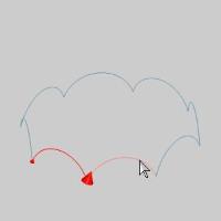
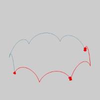
Hover over the end of the next chain, as seen in the image below.
-
Click the entity to set the start of the second chain.
-
Highlight the end of the chain as seen in the image below.
-
Press and hold Shift on the end of the entity to set the end of the chain.

The second chain is added to the Selected Geometry list. -
Continue with these steps, selecting each entity as an individual chain, until all chains are added to the Selected Geometry list.
With all chains selected the Preview appears.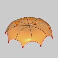
-
Click OK to finalize the Multisided Patch.
The surface is created in the graphics area and aMultisided Patch feature is
created in the CAD Tree.
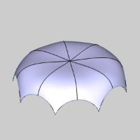
-
To end the function, click Cancel.
This concludes the example.
Example 2
This example will demonstrate how to achieve a different result with
the Multisided Patch function using the same geometry.
-
Press Ctrl+Z to undo the Multisided Patch Surface completed in Example 1.
-
In the Surfaces group, of the Create 3D tab, click
Multisided Patch.
The Multisided Patch parameters display in the Data Entry Manager. -
Highlight the end of the first entity, of the first chain, as seen in the image below.
-
Click the entity to set the start of the chain.
-
Highlight the end of the second entity as seen in the image below.

-
Press and hold Shift on the end of the entity to set the end of the chain.
The first chain is added to the Selected Geometry list.
Tip: While selecting the geometry for a Multisided Patch, you can click the start arrow to change the direction of that cross section, or use the Reverse button after highlighting that chain in the Selected Geometry list of the Multisided Patch Surface parameters in the Data Entry Manager. It is important that all of the chains share the same direction.
-
Hover over the end of the next entity, as seen in the image below.
-
Click the entity to set the start of the second chain.
-
Highlight the end of the following entity as seen in the image below.
-
Press and hold Shift on the end of the entity to set the end of the chain.
The second chain is added to the Selected Geometry list. -
The remaining entities will be selected as a single chain.
Hover over the end of the next entity as seen in the image below.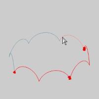
-
Press and hold Shift on the end of the entity to set the start of the chain.
-
Hover over the end of the last entity as seen in the image below.
-
Press and hold Shift on the end of the entity to set the start of the chain.
The third chain is added to the Selected Geometry list, and the preview appears.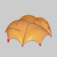
Note: As you can see, using the same geometry, but defining the selected chains differently, can significantly alter the results. If we were to break the arcs, we could adjust the selected chains, and therefore the results, even further. Keep this in mind when using this feature in the future.
-
Click OK to finalize the Multisided Patch.
The surface is created in the graphics area and aMultisided Patch feature is
created in theCAD Tree.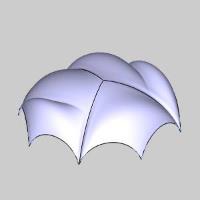
-
To end the function, click Cancel.
This concludes the example.