 Skin Surface
Introduction
This topic will explain the Skin Surface function, and the options found in it. This topic will also describe where to find the function, provide quick steps and an example on how to use it, and provide links to related topics.
The Skin Surface Function
The Skin function is used to create a surface using two or more wireframe chains as cross sections and two or more wireframe chains as rails. To create the surface, you chain select the cross sections, which share the same general direction, and then chain select the rails last, which also share the same general direction.
Tip: Just like the Cross Section surface creation function, this Skin surface creation function can use many cross sections to set the shape of the surface. The Skin function, however, also has the added benefit of rail curves to guide surface creation even further.

Navigation
To open Skin Surface:
-
In the Advanced Surfaces group, of the Create 3D tab, click
 Skin Surface.
The parameters display in the Data Entry Manager.
The Data Entry Parameters
-
 Preview - Select the check box to enable the CAD preview, which displays what the result will be before you create it. Once all geometry is selected, the preview is shown.
  Preview - Clear the check box
to turn off the CAD preview.
Preview - Clear the check box
to turn off the CAD preview.
Cross Section Curves
|
|
|
| The list box will list the entities currently selected for the function. | |
 (Delete All)
- removes all entities from the Selected Geometry list.
(Delete All)
- removes all entities from the Selected Geometry list.Rail Curves
|
|
|
| The list box will list the entities currently selected for the function. | |
|---|---|
- OK - finalizes the function.
- Cancel - exits the function.
Quick Steps - Skin Surface
When creating Skin Surface, you chain select each of the cross sections and rails. Each chain can be one or more entities. Select the cross sections so they share a direction and select the rails so they share a direction.
-
Open the function.
-
Chain select the first Cross Section Curve.
The chain is added to the Cross Section Curves list.
Tip: To chain select an entire chain, hold Shift and click near the end of the last entity to set the start and end of the chain in one click. To select a portion of a chain, click near the end of the first chain entity to set the start of the chain, then hold Shift and click near the end of the last entity to set the end of the chain.
-
Chain select the second Cross Section Curve in the same general direction as the first.
The chain is added to the Cross Section Curves list. -
Repeat this process for the two rails.
The Preview displays once a surface can be created. -
To finalize the surface, click OK in the Data Entry Manager.
The feature is added to the CAD Tree.
You can repeat this process for any other surfaces. -
To close the function, click Cancel.
Example
Note: In the images below, both the Show Axis X-Y and Show Gnomon toggles have been disabled in the Axis X-Y group of the Settings Part > Display dialog.
-
In the Quick Access Toolbar, click
 Open.
Open. -
In the Open dialog box, navigate to C:\BobCAD-CAM Data\BobCAD-CAM V**\Examples.
Note: This is the default install location. If you performed a custom install, navigate to the location in which you installed the software.
-
Select Skin Surface Example, and click Open.
The file opens.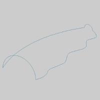
Leave the file in the ISO 2 view. -
In the Advanced Surfaces group, of the Create 3D tab, click
Skin Surface.
The Skin Surface parameters display in the Data Entry Manager and the Cross Section Curves list is given focus to accept selection of chains. -
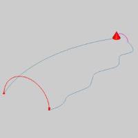
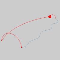
The first step is to select a chain to assign as a Cross Section Curve.
Highlight the entity as seen in the image below.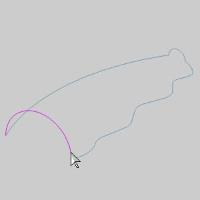
-
Click the entity to set the start of the chain.
-
Highlight the end of the chain, which, for this cross section, can be the same position.
-
Press and hold Shift on the end of the entity to set the end of the chain.

The chain is added to the Cross Section Curves list.
Tip: While selecting the geometry for a cross section, you can click the start arrow to change the direction of that cross section, or use the Reverse button after highlighting that chain in the Selected Geometry list of the Cross Section Surface parameters in the Data Entry Manager. It is important that all of the cross sections share the same direction.
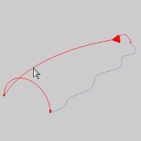
-
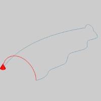
Hover over the end of the next Cross Section, as seen in the image below.

-
Click the entity to set the start of the chain.
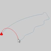
Highlight the end of the chain, which, for this cross section, can be the same position.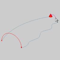
-
Press and hold Shift on the end of the entity to set the end of the chain.
The chain is added to the Cross Section Curves list. - In the Data Entry Manager, click in the Rail Curves list to give it focus.
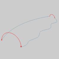
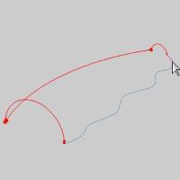
-
Hover over the end of the first Rail, as seen in the image below.
-
Click the entity to set the start of the chain.
-
Highlight the end of the chain, which, for this rail curve, can be the same position.
-
Press and hold Shift on the end of the entity to set the end of the chain.

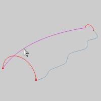
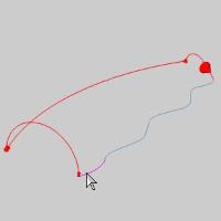
The chain is added to the Rail Curves list. -
The second rail is the first of our chains that is comprised of several entities. Hover over the end of the first entity of the second Rail, as seen in the image below.
-
Click the entity to set the start of the chain.

-
Highlight the end of the last entity of the chain, as seen in the image below.
-
Press and hold Shift on the end of the entity to set the end of the chain.
The chain is added to the Rail Curves list.
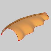
Now, with enough Cross Sections Curves and Rail Curves to create a surface, the Preview appears. -
Click OK to finalize the Skin.
The surface is created in the graphics area and a Skin
feature is created in the  CAD Tree.
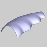
-
To end the function, click Cancel.
This concludes the example.