 Untrim Surface
Introduction
This topic will explain the Untrim Surface function, and the options found in it. This topic will also describe where to find the function, provide quick steps and an example on how to use it, and provide links to related topics.
The Untrim Surface Function
The Untrim Surface function returns a surface back to its natural boundary and removes any holes. This can be used with most organic shaped surfaces, including those that were created using Circular Plane, Rectangular Plane, Planar Surface, or surfaces that had Break Surface applied, to return them to their natural (rectangular) boundary. To perform the function, you select the surface in the Workspace. The surface is automatically untrimmed when selected.
Navigation
To open Untrim Surface function:
-
In the Modify group, of the Create 3D tab, click
 Untrim Surface.
The parameters display in the Data Entry Manager.
The Data Entry Parameters
The function is performed using only geometry selection.
- Cancel - closes the Data Entry Manager.
Quick Steps - Untrim Surface
-
Open the function.
-
Click to select the surface that you want to untrim.
-
The software automatically untrims the selected surface.
The feature is added to the CAD Tree.
You can repeat this process for any other surfaces. -
To close the function, click Cancel.
Example
- In the Quick Access Toolbar, click
 New.
New. - In the Primitives group, of the Create 3D tab, click
 Sphere.
The preview appears.
- Leave the default values as they are and click OK.
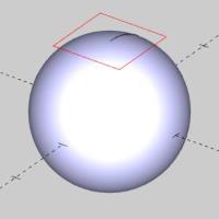
The sphere is created.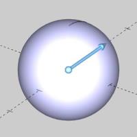
- In the Shapes group, of the Create 2D ribbon,
click
 Rectangle.
The sketch handles of the sphere function disappear. The preview of the rectangle appears.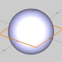
- Update the Dimension group values to Length 1.000, Width 1.000.
- Update the Base Point Z value to 1.000.

- Click OK.
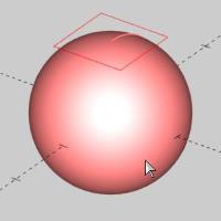
- At the bottom right of the screen, click the down arrow next to the current color.
Color options appear. - Select Black.
The color options disappear.
The result of our projection will now be black. - In the Utilitiesgroup, of the Create 2D ribbon, click
 Project Curves.
The rectangle preview disappears. - Hover over an entity of the rectangle, hold shift and click the entity to select the entire chain.

The entities are added to the Select Curves to Project list. - Click in the Select Surface/Solid list to give it focus.
- Highlight the sphere and click it to add it to the list.

- Click OK.

- In the Modify
group, of the Create 3D tab, click
 Break Surface.
The Break Surface parameters display in the Data Entry Manager.
The Surface/Solid to Break list is automatically given focus to allow selection of the surface or solid to break. - Select the sphere.

The sphere is added to the Surface/Solid to Break list, and the focus is shifted to the Breaking Curves list. - Press S to turn of the shaded view.

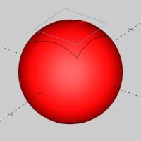
- Hold shift and click an entity of the projected curve to pick the entire chain.

- Click OK.
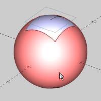
The sphere is broken. - Press S to turn the shaded view on.

- Click Cancel to exit the function.
- In the document toolbar, click
 to enter into selection mode.
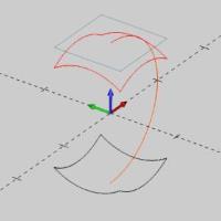
 - Select the sphere, as seen in the image below.
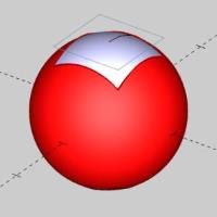
- Delete the sphere.
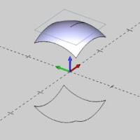
- In the Modify
group, of the Create 3D tab, click Untrim Surface.
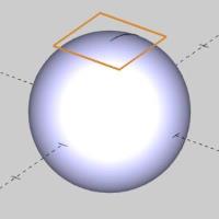
- Select the surface.
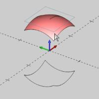
The surface is returned to its unbroken state.
That concludes this example.
Related Topics