 2D Boolean
Introduction
This topic will explain the 2D Boolean functions, describe where to find it, and the options found in it. This topic will also provide quick steps and an example on how to use it, and provide links to related topics.
The 2D Boolean Function
The 2D Boolean functions are used to perform one of three boolean operations on two groups of closed wireframe chains: Add, Subtract, or Intersect. When performing the function, you select two groups of chains that you want to boolean.

Navigation
To open 2D Boolean functions, do one of the following:
-
In the Boolean group, of the Create 2D ribbon, click
 2D Boolean.
This will open the 2D Boolean dialog,. The most recently used 2D Boolean function will be active when this icon is selected. If the 2D Boolean functions have not been used in the document, the 2D Boolean - Add function will be active.
-
In the Boolean group, of the Create 2D ribbon, click the down arrow under
2D Boolean, and select  2D Add.
 -
In the Boolean group, of the Create 2D ribbon, click the down arrow under
2D Boolean, and select  2D Subtract.
-
In the Boolean group, of the Create 2D ribbon, click the down arrow under
2D Boolean, and select  2D Intersect.
The parameters display in the Data Entry Manager.
Note: No matter which option you selected, you will have access to all the 2D Boolean functions in the Data Entry Manager.
The Data Entry Parameters
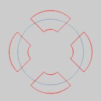
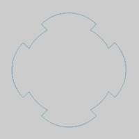
The following image shows example geometry selections for the first and second group. An image of the result is shown below each option.

 Type
Type
|
|
|
Adds the two groups of wireframe chains leaving the remaining (outer) boundary of the two groups. |
|
|

|
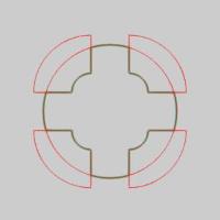
Subtracts the two groups of wireframe chains leaving the remaining boundary of the two groups. |
|
|

|
Intersects the two groups of chains leaving the shared areas of the two. |
Important: The order in which you select the two groups of chains does change the result when using Subtract. Pick what you want to keep in the First Geometry Group, and pick what you want to subtract from that in the Second Geometry Group.
First Geometry Group
|
|
|
| The list box will list the entities currently selected for the function. | |
 (Delete All)
- removes all entities from the list.
(Delete All)
- removes all entities from the list.Second Geometry Group
|
|
|
| The list box will list the entities currently selected for the function. | |
- OK - finalizes the function.
- Cancel - exits the function.
Quick Steps - 2D Boolean
-
Open the function, and select the boolean
type in the Data Entry Manager.
The First Geometry Group list automatically has focus. -
Select the first group of wireframe chains.
This may be one or more chains.
Tip: You may want to prepare the geometry in a way that makes it easier to select. For example, you can place each set of chains on a separate layer and then use Select by Layer while using 2D Boolean. Otherwise, chain selection (hold Shift and click an entity to select the entire chain) is another helpful way to select the chains.
-
Place the focus on the Second Geometry Group list.
-
Select the second group of wireframe chains.
This may be one or more chains.
The Preview appears. -
Confirm the selections to create the final result.
-
Repeat this process for any other groups of chains.
- To close the function, click Cancel.
Example
Part 1) Open the Example File
-
In the quick access toolbar, click
 Open.
Open. -
Navigate to: C:\BobCAD-CAM
Data\**Current Version**\Examples, and select 2D
Boolean Example.bbcd.
-
With 2D
Boolean Example.bbcd displaying in the File
Name box, click Open.
The part opens.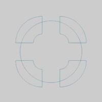
Part 2) Open 2D Boolean
To open 2D Boolean:
- In the Boolean group, of the Create 2D ribbon,
click 2D Boolean.
This will open the 2D Boolean dialog,. The most recently used 2D Boolean function will be active when this icon is selected. If the 2D Boolean functions have not been used in the document, the 2D Boolean - Add function will be active.
The parameters display in the Data Entry Manager, with the focus on the First Geometry Group.
Part 3) Adding Wireframe Groups
In this part, we add the two groups of wireframe chains.
- Confirm that the default option, Add,
is selected in the Data Entry Manager.
- Click to select the circle as the first group
of chains.
The arc is added to the First Geometry Group. - Click in the Second Geometry Group to give it focus.
- Window pick the shapes.
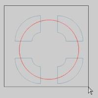

All geometry is added to the list.
Since we have also added the large arc to the Second Geometry Group, our preview is not quite right. - Deselect the large arc.

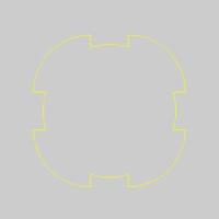
- Click OK.

All geometry is added into a single chain of entities. - Click Cancel to close the Data Entry Manager.
Part 4) Modifying the Feature Using the CAD Tree
The 2D Boolean function is retained in the CAD Tree. This allows for modifications and more as explained in the CAD Tree. Next we use the feature to modify the result.
When you cancel the function, the CAD Tree Manager automatically displays. Notice the 2D Boolean feature in the CAD Tree.
- Click on the CAD Tree Manager to show the CAD Tree.
- In the CAD
Tree, click 2D Boolean
to highlight the result of the feature in the graphics area.
- Notice under the 2D Boolean feature in tree, are two separate items:
 Geometry.
Click each of the Geometry items and notice
that the selected group highlights in the graphics area.
Geometry items and notice
that the selected group highlights in the graphics area.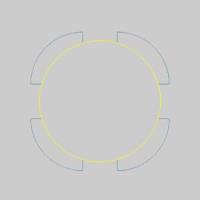

Tip: You can update the geometry for the selected groups using the right-click shortcut menus for each Geometry item.
- Right-click 2D Boolean,
and click Edit.
The Data Entry Manager opens and the geometry is preselected for the 2D Boolean function.
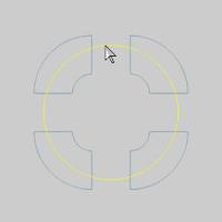
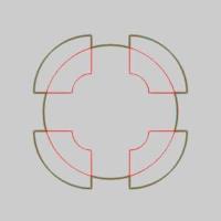
A preview now displays the result of the selected boolean type. - In the Data Entry Manager, click Intersect.
This updates the preview to show the result of the Intersect boolean type. You can see that this results in only the shared regions of the two groups.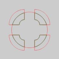
- Click Subtract to update
the preview.
- Click OK to update the
feature.

Note: The Subtract boolean type subtracts the second group from the first, so the order in which you select the groups determines the result. For both the Add and Intersect boolean types, the result is the same regardless of the order in which the groups are selected.
Part 5) Selection Order for Subtract
Next we use the Edit option to modify the geometry selections and show the difference in the result when reversing the selection order with the Subtract boolean type.
- In the CAD
Tree, right-click 2D Boolean,
and click Edit.
This option allows you to completely recreate the feature, including geometry selection. - Next to each Geometry Group list, click
 to remove all geometry from each list.
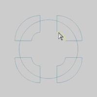
 - With the focus on the First Geometry Group, hold shift and select each of the outer chains, as seen in the images below.
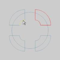

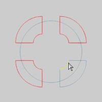

- Click in the Second Geometry Group list to give it focus, and select the large arc.
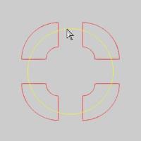
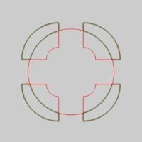
The preview appears. - Click OK.

- Click Cancel to exit the function.
This concludes the example.