 Break Many
Introduction
This topic will explain the Break Many function, describe where to find it, and the options found in it. This topic will also provide quick steps and an example on how to use it, and provide links to related topics.
The Break Many Function
The Break Many function separates entities at the intersection of other entities. To perform the function, you select geometry in the graphics area, and confirm.
Navigation
To open Break Many:
- In the Break group, of the Utilities ribbon, click
 Break Many.
The Parameters open in the Data Entry Manager.
The Data Entry Parameters
 Break Option
![]()
![]()
![]()
![]()
![]()
Entity Selection
Selected Geometry
|
|
|
| The list box will list the entities currently selected for the function. | |
 (Delete All)
- removes all entities from the list.
(Delete All)
- removes all entities from the list.
- OK - finalizes the function.
- Cancel - exits the function.
Quick Steps - Break Many
- Open the function.
The Selected Geometry list automatically has focus. - Select the intersecting entities to be broken.
The entities are added to the Selected Geometry list. - Click OK.
The entities are broken where they intersect each other. - Repeat as necessary.
- Click Cancel to close the function.
Example
- In the Quick Access Toolbar, click
 New.
New. -
In the Entity group, of the Create 2D ribbon, and click
 Line.
Line.
- In the graphics area, sketch two horizontal lines roughly parallel to each other.

- Sketch two more parallel lines vertically, making them cross over both of the horizontal lines.

- Right-click anywhere in the graphics area, and click Entity Summary.
Note that the Quantity of Entities (4).
- To close the dialog box, click OK.
- In the Break group, of the Utilities ribbon, click Break Many.
The Break Many parameters display in the Data Entry Manager.
- In the graphics area, point to each line and notice how each single
entity displays in the Highlight color.
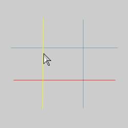
- Point to the lower line so that it displays in the Highlight color, and click to select it.

The line changes to the Selection color.

The line is added to the Selected Geometry list.
-
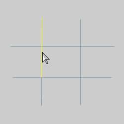
Point to and click to select the left vertical line.

The line is added to the Selected Geometry list.
-
To confirm the selections, click OK in the Data Entry Manager.
-
Point to the horizontal line and notice that it is now two entities.
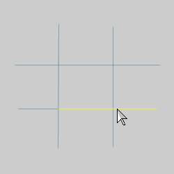

Notice also, the line is not broken at the intersection of the other line. The break only occurs at the intersections of entities chosen for the function.
-
Do the same for the vertical line.

-
Right-click anywhere in the graphics area, and click Entity Summary.
Note the Quantity of Entities (6).
-
To close the dialog box, click OK.
-
In the graphics area, click and drag a window to select all of the entities.

Notice that when using window selection, all entities inside, or intersecting, the window are selected.
- To confirm the selection, press the Spacebar.
This time all entities are broken at their intersections. Point to all of the entities in the graphics area and notice the number of entities.
- Open the Entity Summary and note the Quantity of Entities.
- To end the function, click Cancel.
Tip: If you need to return a broken entity to a single entity, you can use Cleanup and Optimize (and select each segment of the broken entity). This is one of many ways to accomplish such a task. You could also use Undo.
This concludes the example.