 Break Screen
Introduction
This topic will explain the Break Screen function, describe where to find it, and the options found in it. This topic will also provide quick steps and an example on how to use it, and provide links to related topics.
The Break Screen Function
The Break Screen function separates an entity at, or perpendicular to, an arbitrary location. To perform the function, you select geometry in the graphics area and click the break location.
Navigation
To open Break Screen:
- In the Break group, of the Utilities ribbon, click
 Break Screen.
The Parameters open in the Data Entry Manager.
The Data Entry Parameters
 Break Option
![]()
![]()
![]()
![]()
![]()
Entity Selection
Selected Geometry
|
|
|
| The list box will list the entity currently selected for the function. | |
- OK - finalizes the function.
- Cancel - exits the function.
Quick Steps - Break Screen
- Open the function.
The Selected Geometry list automatically has focus. - Select the entity to be broken.
A preview of an X appears on the entity. - Move your mouse in the graphics area, and notice the X tracks your mouse as a perpendicular point on the entity.
- Put the X in the desired place on the entity and click once.
- The entity is broken at the location of the X.
- Repeat as necessary.
- Click Cancel to close the function.
Example
The Break Screen function is used to break a wireframe entity perpendicular to the location at which you click in the graphics area. This function can be used with any wireframe entity in the graphics area. You first select the entity to break, and then you click any location (that is at a right angle to the entity) to break it. (For help drawing wireframe entities, view the CAD_Tutorials.)
With any wireframe geometry (lines, arcs, or splines) in the graphics area, use the following steps.
- In the Break group, of the Utilities ribbon, click Break Screen.
The Break Screen parameters display in the Data Entry Manager.
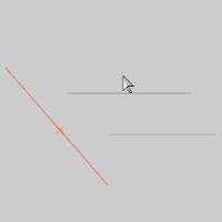
- In the graphics area, highlight the entity you would like to break, and select it.


Notice that the entire entity is displayed
in the Highlight color. This shows that the line is a single entity.
Also, notice the preview of the breaking point displays immediately after the entity is select.
-
Move your mouse away from the selected line, and notice the break point follows your mouse.
- To break the entity, click any location in the graphics area that is perpendicular to the entity.
After clicking in the graphics area, the entity is broken perpendicular to the point that you click. Notice that the entity is no longer displayed in the Selection color.
-
To visually confirm the change, point to either end of the broken entity.
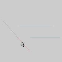
Notice that only half of the line is displayed in the Highlight color.
You can repeat the process explained in this example to break as many entities or break one entity as many times as you want. Be aware that after selecting the entity to break, if you click anywhere in the graphics area that is not perpendicular to that entity, you will receive a Failed In: Break Screen message.
-
To end the function, in the Data Entry Manager, click Cancel.
This concludes the example.