 Spun Profile
Introduction
This topic will explain the Spun Profile function, and the options found in it. This topic will also provide quick steps on how to use it, and provide links to related topics.
The Spun Profile Function
The Spun Profile function is used to pull an overall profile from a surface or solid that is revolved around a particular axis.
|
Part |
Spun Profile |
|
|
|

Navigation
To open Spun Profile:
-
In the Utilities group, of the Create 2D ribbon, click
 Spun Profile.
The parameters display in the Data Entry Manager.
The Data Entry Parameters
Selected Geometry
|
|
|
| The list box will list the entities currently selected for the function. | |
|---|---|
 (Delete All)
- removes all entities from the list.
(Delete All)
- removes all entities from the list.
- Tolerance
- sets the amount of variation allowed when creating a Spun Profile.
 Arc Fit
- creates arcs where possible based on the tolerance selected.
Clearing this check box will produces lines only.
Arc Fit
- creates arcs where possible based on the tolerance selected.
Clearing this check box will produces lines only.
Axis
-
 Pick Axis - the axis will be defined manually, with an existing axis, or a defined vector. Pick Axis - the axis will be defined by selecting a line, or surface edge.
Tip: When the selected geometry to pull the spun profile from is parallel to an X, Y, or Z axis, using Pick Axis is not necessary. When it is askew of an axis, Pick Axis makes it simple. See the images below for a situational example of each.
The following parameters vary depending on the Pick Axis option that is chosen:
![]() Pick Axis
Pick Axis
- Along X Axis - sets the X axis as the axis to unwrap from.
- Along Y Axis - sets the Y axis as the axis to unwrap from.
- Along Z Axis - sets the Z axis as the axis to unwrap from.
- Customized Axis - allows for a custom axis to used for the axis to unwrap from.
![]() Pick Axis
Pick Axis
Rotation Axis
|
|
|
| The list box will list the entity currently selected for the function. | |
Note: The direction defines the vector of the rotation. The direction values are always visible, but can only be edited when Pick Axis is not selected, and the Customized Axis option is chosen. When it is, type in the desired values in the X, Y, Z boxes to define the direction from the Origin Point.
- Origin X - sets the X value for the center of rotation.
- Origin Y - sets the Y value for the center of rotation.
- Origin Z - sets the Z value for the center of rotation.
- Direction X - lists the x value for the vector of the rotational axis.
- Direction Y - lists the y value for the vector of the rotational axis.
- Direction Z - lists the z value for the vector of the rotational axis.
- OK - finalizes the function.
- Cancel - exits the function.
Quick Steps - Spun Profile
-
Open the function, and enter a "1" in the X, Y, or Z Direction box in the Data Entry Manager.
-
Select the surface or surfaces to pull the Spun Profile from.
-
Confirm the selection. (You can click OK, or press Spacebar.)
-
To close the function, click Cancel.
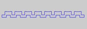
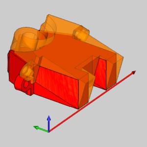
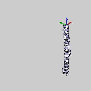
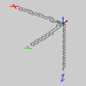
Important: In the images below, you will see a solid and the three different Spun Profile results that were pulled from it. Entering a value in the Y Direction produces the profile labeled Y. Entering a value in the X Direction produces the profile labeled X. Entering a value in the Z Direction produces the profile labeled Z.
|
Solid |
3 results |
|
|
|
Related Topics