 Stretch
Introduction
This topic will explain the Stretch function, and the options found in it. This topic will also give brief description of Dynamic Drawing, the Snap Increment function, will describe where to find the function, provide quick steps on how to use it, and provide links to related topics.
The Stretch Function
The Stretch function is used to modify geometry chains by selecting one or more entities and then moving them, thus stretching the connected entities.
Dynamic Drawing
This function supports Dynamic Drawing which allows you to use a combination of sketching and data entry to create the entities. Prior to confirming the desired result in the function, an adjustable preview is visible. These previews can be modified using the sketch handles, data entry, or a combination of both. The benefit of Dynamic Drawing is that you can quickly utilized the sketch handles to adjust the size, placement, and, or, orientation to get the approximate result, and then use data entry to update to the exact values as needed.
|
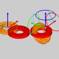
Preview with Sketch Handles |
Final Entities |
|

|
In the images above, we see the preview of the altered position / orientation of the entities which can be adjust with sketch handles, followed by those same entities after their positions / orientations are finalized.
Snap Increment
This function support the use of the snap increment when selecting the location of the entities. The snap increment allows you to get precise results when using mouse selection and helps to reduce data entry modifications.
To learn more, view Snap Increment.
Navigation
To open Stretch:
-
In the Adjust group of the Utilities ribbon, click
 Stretch.
The parameters display in the Data Entry Manager.
The Data Entry Parameters
Selected Geometry
|
|
|
| The list box will list the entities currently selected for the function. | |
 (Delete All)
- removes all entities from the list.
(Delete All)
- removes all entities from the list.
Translate Amount
The Translate Amount can be used to define the amount of movement in the X, Y, and Z axis. The Translate Amount will also show the amount of movement in the X, Y, and Z axis, when the Start Point, and End Point methods are used to set the amount of movement.
- X - amount of movement along the X axis.
- Y - amount of movement along the Y axis.
- Z - amount of movement along the Z axis.
Start Point
The Start Point values are subtracted from the End Point values to define the amount of movement used in the Stretch function. The Start Point can be set, by entering values or by picking a point. The Start Point does not have to be utilized to accomplish a stretch.
|
|
|
| This list box will show the entity currently selected for the function. | |
- X - sets the start point in X.
- Y - sets the start point in Y.
- Z - sets the start point in Z.
End Point
The End Point values are have the values of the Start Point subtracted from them in order to define the amount of movement used in the Stretch function. The End Point can be set, by entering values or by picking a point. The End Point does not have to be utilized to accomplish a stretch. If the End Point values are left alone, and values are entered for the Translate amount, the End Point values will update automatically.
|
|
|
| This list box will show the entity currently selected for the function. | |
- X - sets the end point in X.
- Y - sets the end point in Y.
- Z - sets the end point in Z.
- OK - finalizes the function.
- Cancel - exits the function.
Quick Steps - Stretch
- Open the function.
The Selected Geometry list automatically has focus. - Select the entities to be stretched.
The entities are added to the Selected Geometry list.
An amount is automatically added to the Translate Amount to show the type of movement to be expected. - To stretch the geometry, you can use one of the following methods:
- Translate Amount:
You can enter coordinate values in the Translate Amount section to specify the amount in which the geometry should be stretched.- Update the X, Y, and Z values.
- Update the X, Y, and Z values.
- End Point:
You can use the End Point section to dictate where the geometry should be stretched to, either with coordinates, or by selecting a point from the graphics area.- The End Point can be set by either:
- Selecting a location in the graphics area using the mouse. Make sure the End Point list box has focus, and then, simply click in the graphics area to select a location.
- Entering a location using the X, Y, and Z list boxes.
- Selecting a location in the graphics area using the mouse. Make sure the End Point list box has focus, and then, simply click in the graphics area to select a location.
- The End Point can be set by either:
- Start Point, and End Point:
You can define, both, the Start Point, and the End Point.- The Start Point can be set by either:
- Selecting a location in the graphics area using the mouse. Make sure the Start Point list box has focus, and then, simply click in the graphics area to select a location.
- Entering a location using the X, Y, and Z list boxes.
- Selecting a location in the graphics area using the mouse. Make sure the Start Point list box has focus, and then, simply click in the graphics area to select a location.
- The End Point can be set by either:
- Selecting a location in the graphics area using the mouse. Make sure the End Point list box has focus, and then, simply click in the graphics area to select a location.
- Entering a location using the X, Y, and Z list boxes.
- Selecting a location in the graphics area using the mouse. Make sure the End Point list box has focus, and then, simply click in the graphics area to select a location.
- The Start Point can be set by either:
- With the values updated, and the preview showing the desired result, press OK.
- Repeat as necessary.
- Click Cancel to close the function.