 Options
Introduction
This topic explains the Options page found in the Advanced Rough operation of the Mill 3 Axis Wizard. The Advanced Rough operation provides a powerful roughing strategy with three cut patterns: an offset pattern, parallel pattern, and a high-speed machining pattern with automatic tool engagement control. Intermediate Slices, Rest Roughing, and Flatlands detection can be used as well as many other controls explained in this topic.
Operation Stock
The Advanced Rough operation always uses a stock recognition for the toolpath calculation. By default, the stock definition from the Stock Wizard is used. You can also specify the stock to use by assigning geometry to the Operation Stock item in the CAM Tree. Operation stock allows you to remove unnecessary air cutting from the operation by passing stock for only the area that you want to cut. There are no settings needed in the wizard to use stock recognition for the Advanced Rough operation. The stock definition from the Stock Wizard is always used unless you assign Operation Stock.(View Selecting Operation Stock for more help.)
Tip: You can use simulation to save the stock model as an .stl file, which can then be used as Operation Stock. To learn more, view How to Save Simulation Stock as STL.
 Options
Rest Roughing
Calculates the toolpath to remove all the non-machined areas remaining
from the previous roughing tool. The previous tool is used to
identify accurately the areas on a 3D component by sweeping the diameter
across the whole part being machined. In this way any non-machined
areas are identified and passed to the system and the toolpath is
calculated. The Rest Roughing toolpath does not require the whole
part to be machined again. It machines only those areas that are left
behind by the previous tool. On intricate parts, multiple rest rough
toolpaths are required to remove as much material as possible before
running semi finishing or finishing toolpaths. In Rest Roughing toolpaths
you normally use a smaller step down (as the cutter size reduces)
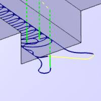
than the cutter used for the previous roughing toolpath. The following
is an example of using the Advanced
Rough feature for rest machining,
along with an image showing the rest roughing strategy in blue.


![]() - With this check box cleared, Rest Roughing will not be used.
- With this check box cleared, Rest Roughing will not be used. ![]() - With this check box selected, Rest Roughing will be used, and the following options will become available to allow you to specify how the rest roughing is to be handled.
- With this check box selected, Rest Roughing will be used, and the following options will become available to allow you to specify how the rest roughing is to be handled.
Note: The Use Previous Operation check box doesn't display unless you have another operation previous to the current operation in the feature.
- Use
Previous Operation
 - Clear the check box to manually enter the tool parameters of the previous
roughing operation.
- Clear the check box to manually enter the tool parameters of the previous
roughing operation. - Select the check box to have the system automatically set the Rest Roughing
parameters using the tool parameters of a roughing operation that is previous
to this operation in the feature.
- Select the check box to have the system automatically set the Rest Roughing
parameters using the tool parameters of a roughing operation that is previous
to this operation in the feature.- Previous
Tool Diameter - set this to the
diameter of the previous tool used to rough the part. This value must
be larger than the tool being used for the rest roughing operation.
- Previous
Tool Corner Radius - set this to
the corner radius of the previous tool used to rough the part.
- Previous
Offset Type - The Offset Type determines if the allowance from
the previous operation was applied to the entire model or separately
for the bottom and sides of the part. Select one of the following
options and then type the allowance value used in the available allowance
boxes.
- Global
- calculates the toolpath applies a single allowance value
to the entire model using the Allowance XYZ value.
- Allowance
XYZ - is the amount of material left on the
entire model (XYZ).
- Allowance
XYZ - is the amount of material left on the
entire model (XYZ).
- Side
and Bottom - allows you to specify separate allowances
for the side (XY) and bottom (Z) of the part.
- Side
Allowance - is the amount of material left
on the sides of the part (XY).
- Bottom
Allowance - is the amount of material left
on the bottom of the part (Z).
- Side
Allowance - is the amount of material left
on the sides of the part (XY).
- Global
- calculates the toolpath applies a single allowance value
to the entire model using the Allowance XYZ value.
- Detect stock thicker than - allows you to focus the toolpath on stock consisting of a particular range of thickness. Setting a value here will force the toolpath to ignore any stock whose thickness does not meet or exceed this value.
- Previous
Tool Diameter - set this to the
diameter of the previous tool used to rough the part. This value must
be larger than the tool being used for the rest roughing operation.
Machine Flatlands
Flatlands
is designed to finish flat areas of a part, and it is best suited for
machining large flat areas at multiple Z-levels.
![]() - Clear this check
box to not allow flatland machining.
- Clear this check
box to not allow flatland machining.![]() - Select this check
box to allow flatland detection which creates an optimized finishing toolpath
for flat areas.
- Select this check
box to allow flatland detection which creates an optimized finishing toolpath
for flat areas.
- Min.
Width of Flatlands - sets the minimum width of flat areas that
are included in the flatlands machining.
- Max. Width
of Flatlands - sets the maximum
width of flat areas that are included in the flatlands machining.
- Clear the check box to only set a minimum width of flat areas that are
included. - Select the check box to set a maximum width of flat areas that are included.
Important: The Flatlands feature must use flat-end mills or bullnose mills.
|
|
Boundary Options
Boundaries are used to contain the toolpath of the operation to stay within the specified area. The Boundary Options determine where the tool cuts when it reaches the boundary in one of three ways.
-
 Center of
Tool - forces the center of the tool to cut directly on the
specified boundary.
Center of
Tool - forces the center of the tool to cut directly on the
specified boundary.

-
 Tool Inside
- forces the entire tool to stay inside of the boundary. (This offsets
the toolpath to the inside of the boundary by the tool radius.)
Tool Inside
- forces the entire tool to stay inside of the boundary. (This offsets
the toolpath to the inside of the boundary by the tool radius.)

- Offset - is used to add an additional offset to the location of the tool at the boundary when using Tool Inside or Tool Outside. When using Tool Inside, the tool stays inside of the boundary by the specified distance. When using Tool Outside, the tool goes outside of the boundary by the specified distance. Note that positive or negative values are supported.
-
Tool Outside
- forces the entire tool to go outside of the boundary. (This offsets
the toolpath to the outside of the boundary by the tool radius.)

- Offset - is used to add an additional offset to the location of the tool at the boundary when using Tool Inside or Tool Outside. When using Tool Inside, the tool stays inside of the boundary by the specified distance. When using Tool Outside, the tool goes outside of the boundary by the specified distance. Note that positive or negative values are supported.
Other
- Smoothing
- Clicking on the Smoothing button will launch the Smoothing dialog
box. The Smoothing dialog box will give access to some, or all, of the
following options, depending on the pattern chosen.
- Smooth Corners - Select the check box to create fillets in the sharp corners
of the toolpath. The fillet is not applied to the outer contour as it
is with Smooth Final Contour. When selected, the Smooth Distance/Stepover
% parameter becomes available as well as the Smooth Final Contour option.
- Clear the check box to turn off Smooth Corners.
- Smooth Distance/Stepover % - With the Smooth Corners check box selected, the Smooth Distance/Setpover % sets the
radius of the fillet as a percentage of the stepover distance.
- Smooth Distance/Stepover % - With the Smooth Corners check box selected, the Smooth Distance/Setpover % sets the
radius of the fillet as a percentage of the stepover distance.
- Smooth Links -
Select the check box to smooth the links within a group. The last segments
of the previous contour and the first segments of the next contour are
trimmed. The connecting link connects diagonally. In the case of an S-Link
the connection is an S-type link.
- Clear the check box to turn off Smooth Links.
- Gap
Size/Stepover % - With the Smooth Links check box selected, the Gap Size/Stepover % sets the distance over which the s-link
moves are applied as a percentage of the stepover amount.
- Gap
Size/Stepover % - With the Smooth Links check box selected, the Gap Size/Stepover % sets the distance over which the s-link
moves are applied as a percentage of the stepover amount.
- Smooth Final Contour - With the check box cleared, the Smooth Final Contour option is not used.
- Select the check box to create fillets in the sharp corners of outer contours.
The Smooth Distance/Stepover % parameter becomes available.
- Smooth Distance/Stepover
% - sets the radius of the
fillet as a percentage of the stepover distance.
- Smooth Distance/Stepover
% - sets the radius of the
fillet as a percentage of the stepover distance.
- Ignore Small Contour
- Clear the check box to turn off Ignore Small Contour. - Select the check box to remove small pockets and segments which
are not necessary to machine. The size of these segments must be defined
as a percentage of the tool diameter. The Threshold Value in % of Tool
Diameter parameter becomes available.
- Threshold Value in
% of Tool Diameter - sets the
size of the small segments to remove as a percentage of the tool
diameter.
- Threshold Value in
% of Tool Diameter - sets the
size of the small segments to remove as a percentage of the tool
diameter.
- Remove Corner Pegs
- Clear the check box to turn off Remove Corner Pegs. - Select the check box to add extra
tool movement in corners, removing the rest material; for use when a stepover
greater than 50 percent results in small pegs of material remaining in
the corners.
- Smooth Corners
Processing
Sorting
-
By Area - machines an entire area of the part before
moving on to the next.
-
By Level - machines all areas of the part to the
current pass depth before beginning the next pass.
Intermediate Steps
- After
Last Depth Step - cuts all intermediate slices for the entire
model after the final depth step of the operation.

- After Each Depth Step - cuts the
intermediate slices for each depth step immediately after finishing
each depth.


Break through amount
When using the Advanced Rough with Adaptive Roughing, the Break through amount becomes available. This will dictate how far the pocketing moves will continue on an open pocket before coming back to clean up the edges.
| Less | More |
|

|