 Geometry Selection and Select Mode
Introduction
This topic will explain selection mode, explain the different selection methods, explain how to confirm selection, cancel selection, provide examples of those selection methods, as well as provide links to related topics.
Selection Mode
To select geometry in the graphics area, selection mode must be active. While selection mode is made active automatically when entering most CAD functions, and while selecting geometry for CAM features, you can also get into selection mode manually by:
- In the Selection group, of the Home ribbon, click
 Select Mode.
 - On the Document Toolbar,
click the
 Select Mode icon.
 - Right-click in the graphics area and click Select to enable/disable section mode. Once in selection mode you can also right-click in the graphics area and click Cancel to exit selection mode.
Note: In each case, repeating that step will disable selection mode.
Selection Methods
Single Selection
For single selection, with selection mode active, you click the entity that you want to select. As you point to the entity, the entity is displayed using the Highlight color to show that it can be selected. The entity types that can be selected are determined by the Selection Mask. Once an entity is selected, it is displayed using the Selection color. You can continue to select single entities one at a time. The selection filters further define how single selection works. This includes only adding or removing entities or both (Add/Remove). Click here to jump to the example for this method located further down the topic.
Chain Selection
For chain selection, with selection mode active, you press and hold Shift, and click a chain of connected entities to select the entire chain (curve). Chain selection can also be used to define a direction for the chain, for example, when certain CAD functions, such as Cross Section, are active. For these functions, to define the direction of a chain, you first click near the end of the first entity in the chain (to set the chain start and direction), and then press and hold Shift, and click near the end of the last entity in the chain (to define the end of the chain). You can also press and hold Shift and click near the end of the chain (to eliminate the first step), for example, when selecting an open chain. Click here to jump to the example for this method located further down the topic.
Window/Region Selection
For window selection, with selection mode active, you drag the mouse to create a window. This means that you click and hold the left mouse button while moving the pointer to create a window. All entities that are within the window are selected. The entities do not have to be completely contained within the window to be selected. This method can be used to modify geometry, assign geometry to CAM features, or to select geometry for some CAD functions. Click here to jump to the example for this method located further down the topic.
Snap Point Selection
Many CAD and CAM features utilize the snap points of an entity. To show the snap points of an entity for these functions, hover over a wireframe entity, or solid edge, and the snap points will appear. You can then select one of the available snap points. Be aware that you do not have to click a snap point directly in order to select it (you don't have to show them first either). For functions that support snap points, the snap point of the entity that is closest to the location that you click is automatically selected. Click here to jump to the example for this method located further down the topic.
Confirming Geometry Selections
When selecting geometry for CAD functions, the geometry is added into the geometry selection lists. When all appropriate geometry is selected, a preview can be generated. When all appropriate geometry is selected, the function can be completed using one of the methods below. When selecting geometry for CAM features, you must confirm the selections using one of these same steps.
To confirm (finalize) geometry selections that you have made, do one of the following:
- Right-click in the graphics area,
and click OK.
- In the active dialog (CAD function, or CAM Geometry Selection), click OK.
- Press the Spacebar.
- In the top right-hand corner of the graphics area,
click
 (OK).
(OK).
Cancel Selection Mode
To cancel Selection Mode or a CAD function, do one of the following:
-
Right-click in the graphics area, and click Cancel.
-
In the top right-hand corner of the graphics area, click
 Cancel.
-
Press Esc.
Examples
Single Selection
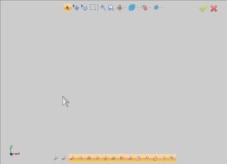
- With Selection Mode active, over hover the first line.

The line highlights. - Click the line to select it.
- Hover over the arc to highlight it.

The arc highlights. - Click the arc to select it.

The arc is selected. - Move your mouse over the Line Mask icon and click to toggle the Line Mask.
Now, lines cannot be selected. - Hover your mouse over the next line to try to highlight it.
Notice with the Line Mask turned off, you cannot highlight or select lines. - Hover your mouse over the previously selected arc.
Notice arc, can still be highlighted, and selected.
This goes for all the other entity types whose mask types still selected.
Chain Selection
Chain Selection: Direction
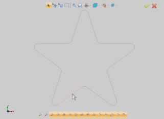
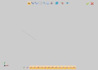
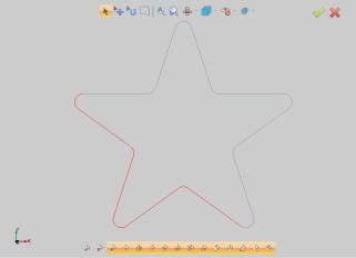
You can control the direction of your chain selection by choosing one side of the entity or the other. The chain will always pull from the back of the chain toward your mouse. In the example below you can see a simple chain made of five lines. You will notice, depending on which side of the center line we are on when we chain select will affect which lines are selected. 
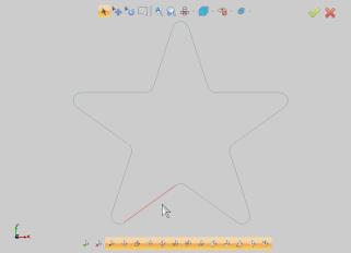
- Hover over the right side of the line, and hold Shift.
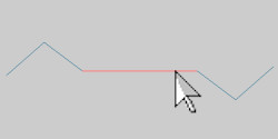
- With Shift still held down, click the line.

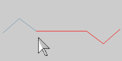
- Repeat the process to deselect the entities.
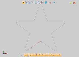
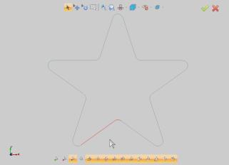
- Now hover over the left side of the line and hold Shift.

- With Shift still held down, click the line.
Note: In this section we see how we can control the entities that are selected with the direction of the chain selection. If the above example were a closed chain, like a square, the result would be the same regardless of the which side of the entity we were on. In some cases, you need to chain select a select portion of a closed chain. This is shown next.
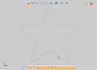
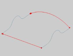
Chain Selection: Start and End
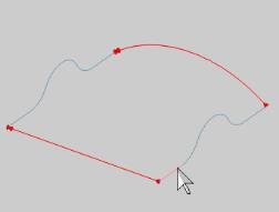
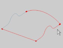
To demonstrate how to use the chain selection method to select a portion of a closed chain, we will use the Skin function to help illustrate the start and stop positions. This same method can be used outside of a CAD function, but when using many of the 3D CAD functions, the start and end points of the selected chain are shown with direction arrows which is ideal for this example. In the images below, you will see the wireframe entities we will use to make our surface.


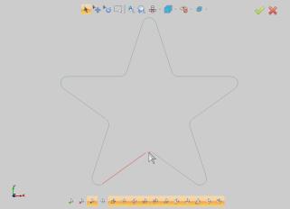
- Hover over the left side of the line, hold Shift and left-click.
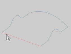

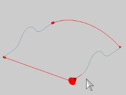
The entire chain is selected and added to the Cross Section Curves list. For this function we need four separate chains, so we delete this chain from the list. - Hover over the left side of the line, and left click.
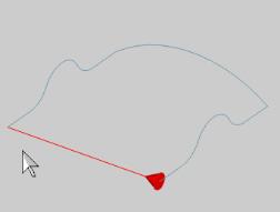
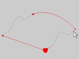
The start of the chain is defined. - Hover over the left side of the entity, hold shift and left-click.
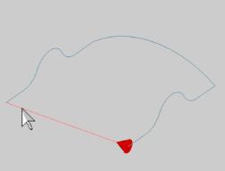
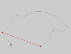
The end of the chain is defined, and the chain is added to the Cross Section Curves list. - Repeat the process for the arc on the opposite side, using the left side of the arc so the direction of the chains match.
The chain is added to the Cross Section Curves list. - Click in the Rail Curves list box to give it focus.
- Find the first entity in the next chain, and hove your mouse over the end of it, and click once.
The start of the chain is defined. - Now find the last entity in the desired chain, hover over the end of it, the hold Shift and left-click.
The end of the chain is defined, and the chain is added to the Rail Curves list. - Repeat the process with the opposite chain, being sure to keep the same direction.
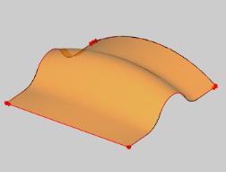
As soon as the chain is defined, the chain is added to the Rail Curves list, and the preview is displayed. - Click OK.
The surface is created.
Chain Selection: Broken chains
Occasionally, you may attempt to pick an entire chain, and notice only a portion of the chain selected. In this section, we will illustrate using chain selection to find issues with our geometry.
- Hover over the right side of the line, and hold Shift.

- With Shift still held down, click the line.
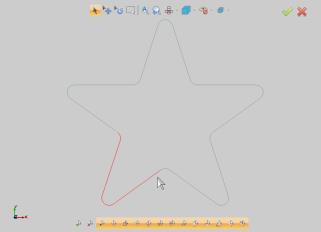
In this case, the full chain is not selected. - Repeat the process to deselect the entities.
- Now hover over the left side of the line and hold Shift.
- With Shift still held down, click the line.

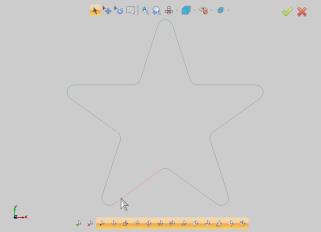
In this case, the full chain is not selected. - Zoom into the area where the selections stopped.
Notice there is a break in our chain.
Tip: Using the chain selection method is an excellent way to test your geometry to ensure there are no breaks, doubles, or unexpected intersections.
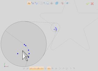
Chain Selection: Pro Tip 1
There may be times that chain selection produces seems as if a single entity was left out of the selection, as seen in the following image:
This can be due to a double entity created by mistake, or perhaps on a separate layer. However it is created, adding it to a feature can create issues. To correct the issue seen above:
- Window pick the entire selection.

When you release the mouse, everything that was selected will be deselected, and vice versa.
With our problem entity selected, simply hit delete.
Chain Selection: Pro Tip 2
There may be times that chain selection looks perfect, but actually hides a double entity.

In the first pro tip, our double entity was clear. In some cases, they are not as easy to spot. Looking closely, at your selected geometry, you may notice the selection color of one entity is a little off. It may look as though it shares a little of the color of an unselected entity. If that happens its evidence of a double entity. To ensure you haven't accidentally left an entity that will give you trouble later, here is an easy way to test:
- With the entire chain selected, press Ctrl+X to cut the selected entities and place them on the clipboard to be pasted later.
- In this case we are left with an entity that should not be there.
Simply select the entities.

- With our problem entity selected, delete it.
- Now press Ctrl+V to paste our previously cut entities back into the graphics area.

Our clean chain is now, most definitely, the only thing left.
If there is no entity, you can immediately paste the geometry back, or use Undo.
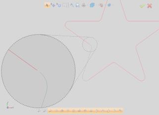
Window/Region Selection
While chain selection is the best way to make sure you have not selected any unintended entities, window selection is a quick way to select many entities, and even many chains, at the same time:
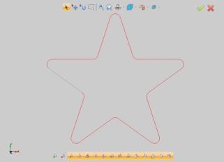
- In the graphics area, left-click and hold on one diagonal of the rectangle area you intend to select. In the image below, we use the top left corner.
- While holding down left-click, drag your mouse to the opposite corner, and then release left-click.
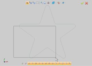
The area within the selection window is selected.
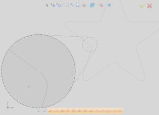
Snap Point Selection
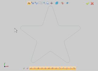
When placing items in the graphics area, you can utilize the snap point of other entities to place them where you intend. In the following steps we are attempting to place a point at the arc center of an existing radius:
- While in the Point function, hover over the arc for a moment and the possible snap points will appear.

Once the snap points appear, you can move your mouse away from the entity, and the snap points will remain until the snap points of another entity are activated, or the function is canceled. - Move to the desired snap point to highlight it.

- Click the snap point to place the point.
Related Topics
To learn about modifying the types of entities that can be selected, view the Selection Mask Dialog Box.
To learn about modifying geometry, view Modify Entity.
To learn about selecting geometry for CAM features, view Geometry Selection: CAM Features.