 Fillet /
  Chamfer
Introduction
This topic will explain the Fillet / Chamfer function, will explain where to find the function, and explain the options found in it. This topic will also explain creation with quick steps, examples, and provide links to related topics.
The Fillet / Chamfer function
The Arc Fillet function creates an arc, of a defined radius value, tangent to two selected entities. The Chamfer function creates a line between two entities using an angle and/or distance.
Navigation
To open Fillet / Chamfer, do one of the following:
-
In the Cornersgroup, of the Create 2D ribbon, click
 Fillet.
 -
In the Cornersgroup, of the Create 2D ribbon, click
 Chamfer.
The parameters display in the Data Entry Manager.
The Data Entry Parameters
Type
![]() Fillet - selecting this option
will enable the creation of fillets.
Fillet - selecting this option
will enable the creation of fillets.
![]() Chamfer - selecting this option
will enable the creation of chamfers.
Chamfer - selecting this option
will enable the creation of chamfers.
Picking Method
![]() Between 2 Entities - requires clicking
one entity and then the other to create the fillet or chamfer between
the two entities.
Between 2 Entities - requires clicking
one entity and then the other to create the fillet or chamfer between
the two entities.
![]() Single Corner Click - a single click
where two entities meet creates the fillet or chamfer.
Single Corner Click - a single click
where two entities meet creates the fillet or chamfer.
![]() Chains - allows you to select an
entire chain of entities to apply the fillet or chamfer to all possible
locations on the chain. With the Chains option chosen, the Selected Geometry list becomes available.
Chains - allows you to select an
entire chain of entities to apply the fillet or chamfer to all possible
locations on the chain. With the Chains option chosen, the Selected Geometry list becomes available.
Selected Geometry
|
|
|
| The list box will list the entities currently selected for the function. | |
 (Delete All)
- removes all entities from the list.
(Delete All)
- removes all entities from the list.Parameters
 Fillet
The available Parameters vary based on the
Type chosen. Listed below are the Parameters for the Fillet option.
- Radius - sets
the distance from the center of the arc to the circumference of
the arc.
- Trim
![]() Select the check box to have the selected
wireframe entities trimmed when creating the arc.
Select the check box to have the selected
wireframe entities trimmed when creating the arc.
![]() Clear the check box to create the arc without trimming the selected entities.
Clear the check box to create the arc without trimming the selected entities.
Chamfer
The available Parameters vary based on the Type chosen. Listed below are the Parameters for the Chamfer option.
-
Angle - sets the angle of the chamfer from the selected entities.
- Distance 1 - sets
the distance from the edge of the (first) selected entity to start
the chamfer.
- Distance 2 - sets the distance from the edge of the (second) selected entity to start the chamfer.
Chamfer Method
There are three methods to select from when creating chamfers. The selected option determines which parameters become available.
- Angle & Distance 1 - uses
the Angle and Distance 1 values to create the chamfer.
- Angle & Distance 2
- uses the Angle and Distance 2 values to create the chamfer.
- Distance 1 & Distance 2 - uses the Distance 1 and the Distance 2 values to create the chamfer.
- OK - creates the
fillet or chamfer when using the Chain picking method.
- Cancel - closes the function.
Quick Steps - Fillet / Chamfer
Between 2 Entities Picking Method
- Set the Parameters as needed.
- Select the first entity to fillet/chamfer.
The entity turns the selection color. - Hover over the next entity to be filleted/chamfered.
The preview appears, showing what the function will do.
Select the next entity.
The function is completed. - Repeat as necessary.
- Click Cancel to exit the function.
Single Corner Click Picking Method
- Set the Parameters as needed.
- Hover over the first entity to fillet/chamfer.
The preview appears, showing what the function will do.
Select the entity.
The function is completed. - Repeat as necessary.
- Click Cancel to exit the function.
Chains Picking Method
- Set the Parameters as needed.
- Select a chain to fillet.
The chain is added to the Selected Geometry list.
The preview appears, showing what the function will do. - Add chains to the list as necessary.
- With all chains added to the list, click OK.
- Click Cancel to exit the function.
Example
This example will demonstrate how to use the Chamfer and Fillet functions.
Note: In the images below, both the Show Axis X-Y and Show Gnomon toggles have been disabled in the Axis X-Y group of the Settings Part > Display dialog.
Part 1) Creating a Shape
- In the Quick Access Toolbar, click
 New.
New. - In the Shapes group, of the Create 2D ribbon, click
 Shape Library.
 - Click the image of the Disk shape in the Data Entry Manager.
The Shape Library dialog appears.
-
Select the Beveled
Rectangle using the
 icon.
icon.
The Beveled Rectangle parameters display in the Data Entry Manager and the Preview appears showing the default values.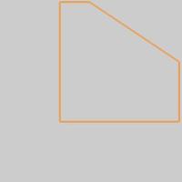
-
Click OK to
accept the default values.
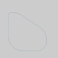
The Beveled Rectangle is created in the graphics area, and an
Beveled Rectangle feature is added to the  CAD Tree.
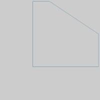
-
Utilize the shortcut for
 Fit
All by pressing F.
Fit
All by pressing F.
The Beveled Rectangle is centered in the graphics area.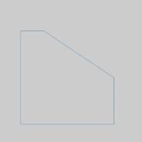
-
Press Ctrl+A to
Utilize the shortcut for Select All.
The geometry highlights. -
Press Ctrl+C to
Utilize the shortcut for Copy.
We will use this copy later to quickly paste this geometry back into
the graphics area.
Part 2) Using the Between 2 Entities Method
-
In the Cornersgroup, of the Create 2D ribbon,
click Chamfer.
The Fillet / Chamfer parameters display in the Data Entry Manager with Chamfer selected as the Type.
Notice the Picking Method is set to the default of Between 2 Entities, and the Chamfer Method is set to the default of Angle-Distance 1. -
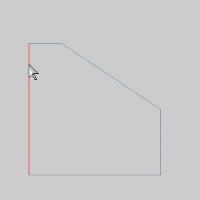
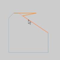
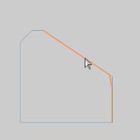
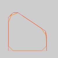
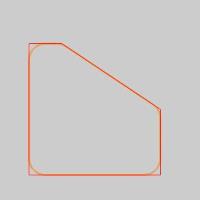
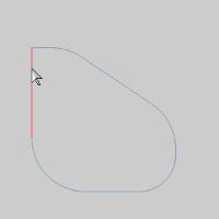
With the Parameters left at their default
settings, click the left hand vertical line as seen in the image below.
-
Hover over, but do not select, the
angled line on the right as seen in the image below.
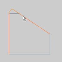
Notice this line could be selected even though it is not currently connected to our first line. Because the two could intersect, they can be extended to create the chamfer. -
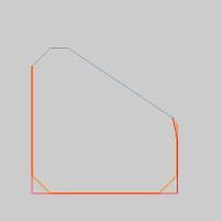
Click the top horizontal line as seen in
the images below.
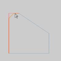
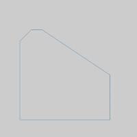
a 45° Chamfer is created.
Part 3) Using the Single Corner Click Method
-
In the Picking
Method group, select the Single
Corner Click method.
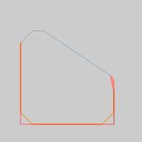
-
Hover over, but do not select, the
top half of the angled line on the right as seen in the image below.
Take a moment to notice how these Parameter values are being applied.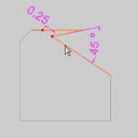
-
Hover over, but do not select, the
bottom half of the angled line on the right as seen in the image below.
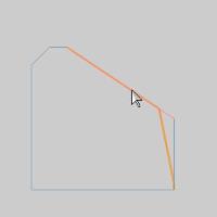
Take a moment to notice how these Parameter values are being applied.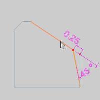
Part 4) Using the Angle-Distance 2 Parameter
-
Change the Chamfer
Method to Angle - Distance
2.
-
Hover over, but do not select, the
bottom half of the angled line on the right as seen in the image below.
Take a moment to notice how these Parameter values are being applied.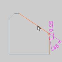
- Click the bottom half of the angled line
on the right to achieve the result seen in the image below.
Part 5) Using the Chains Method
-
Change the Picking
Method to Chains.
-
Hover over the bottom horizontal line as
seen in the image below.
-
Hold Shift
and click the line to chain
select the entire chain.
As you can see, we can pick entire chains to apply chamfers and fillets to. We can also deselect entities as we will see in the next step. -
Move your mouse above the geometry and to
the left without going past it. Hold the left mouse button and drag
a window down and just above the last chamfer we created, as seen
in the image below.
-
Release the left mouse button to deselect
the enclosed geometry.
-
Now we will remove the chamfer from our selected
chain by using the Selected Geometry
list. Click on Line-8 in
the Selected Geometry list.
The entity highlights in the graphics area.
Note: The names of the entities in the Selected Geometry list are based on the number of entities in the file. If other entities have been created in this file the name of the entity in the Selected Geometry list may differ.
-
With Line-8 highlighted, click the
 (Delete)
or press Delete on your keyboard.
(Delete)
or press Delete on your keyboard. 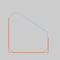
The entity is removed from the list and is no longer highlighted in the graphics area.
Part 6) Using the Distance 1-Distance 2 Parameter
-
Change the Chamfer
Method to Distance 1-Distance
2.
-
Change the Distance
1 value to 0.7500.
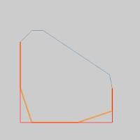
The preview updates. Notice how the 0.7500 value is being applied.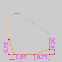
-
Click OK
to confirm the chamfers.
Part 7) Pasting Geometry
-
In the Layers Manager,
right-click and select Add New Layer.
A new layer is created. Upon creation the name is highlighted to allow you to rename. -
Name the new layer Fillet
and press Enter.
The layer is renamed. -
Right-click the Fillet
layer and select Active Layer.
The Fillet layer is active and future CAD creation will be on this layer. -
Right-click the CAD
layer in the Layers tab of
the Layer Manager
and select Hide to hide shape with Chamfers.
-
Click in the graphics area and press Ctrl+V to paste the geometry copied
in the beginning of this example.
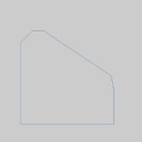
Part 8) Creating Fillets with the Chains Method
-
Change the Type
to Fillet.
-
Hover over the bottom horizontal line as
seen in the image below.
-
Hold Shift
and click the line to chain
select the entire chain.
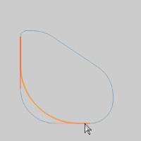
The preview appears. Notice that each angle has a fillet applied. -
In the Parameters group, change the Radius value to .7500.
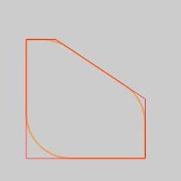
The preview appears. Notice that a fillet is only applied where possible. -
Click OK
to confirm the fillets.
Part 9) Using the Single Corner Click Method
-
In the Picking
Method group, select Single
Corner Click.
-
In the Parameters
group, set the Radius value
to 0.3750.
-
Click the right side of the lower horizontal
line, as seen in the image below.
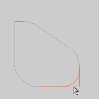

The fillet is created.
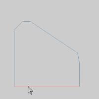
Part 10) Using the Between 2 Entities Method
-
In the Picking
Method group, select Between
2 Entities.
-
In the Parameters
group, set the Radius value
to 0.1250.
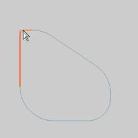
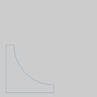
-
Click the left vertical line as seen in the
image below.
-
Click the top horizontal line as seen in
the image below.
Part 11) Creating a New Layer
-
In the Layers Manager,
right-click and select Add New Layer.
A new layer is created. Upon creation the name is highlighted to allow you to rename. -
Name the new layer New
Fillet and press Enter.
The layer is renamed. -
Right-click the NewFillet layer and select Active Layer.
The New Fillet layer is active and future CAD creation will be on this layer.
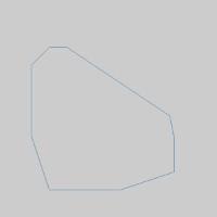
Part 12) Creating a Separate Fillet
-
Clear the Trim
check box above the OK button.
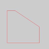
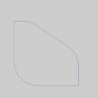
This will allow us to create a fillet without trimming any of our existing entities. - In the Parameters
group, change the Radius value
to 1.2500.
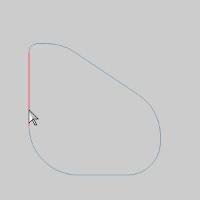
-
Click the left vertical line as seen in the
image below.
-
Click the bottom horizontal line as seen
in the image below.
The fillet is created. - Right-click the Fillet
layer in the Layers Manager,
and select Hide to hide shape with Fillets.

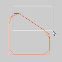
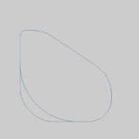
Tip: This can be helpful when we are trying to avoid altering the original shape. In the images below, we have used the new fillet to create a closed shape that can be used to do an Extrude Cut from a extrusion of our original shape.
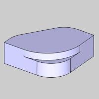
That concludes these examples.