Parallel to Multiple Curves
Introduction
The Parallel to Multiple Curves feature creates a toolpath as an offset of a leading curve. The neighboring toolpath segments are parallel to each other. An important point here is that the cuts are not simply copied next to each other; every new cut is an offset of the previous cut. When selecting the curve geometry, select the curves directly from the part. When using a single drive surface, you can only select one curve from which to create a parallel toolpath. When using multiple drive surfaces, you can then select multiple curves to use. Each curve is only used for the drive surface nearest to that curve.

Surface Paths
Pattern
Edit curves
-
Edge Curves - enables selection mode for you to select the lead Edge curve geometry.
-
Drive surfaces - enables selection mode for you to select the Drive Surfaces geometry. The toolpath is applied to the selected surfaces.
-
Drive surfaces offset - is used to leave stock remaining on the part. You can type positive or negative values.
To learn about the remaining Surface Paths parameters, view the Surface Paths.
To learn about the other Multiaxis Parameters, view the Multiaxis Wizard.
How it Works
-
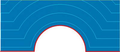
The toolpath segments are offset parallel to the curve (red), not copied.
-
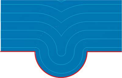
When the curve has arcs or similar shapes, at some point the cuts must interleave. Where the arcs collapse sharp corners are generated.
-
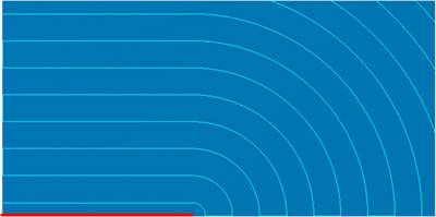
If the curve doesn't cover the whole surface edge, the cuts end in an arc.
Note:
• The curve must be located exactly
on the surface edge. If you don't have a proper leading curve aligned
to the edge, an incorrect toolpath can be generated.
• If you select multiple curves, only
the first curve will be used. For more complex models it is difficult
to provide the correct leading curve to machine the whole model.
• You can define a margin to get the exact
position where the tool is located at the edge with a certain distance.
• It is possible to use multiple curves
for multiple surfaces. Each curve is used only for the nearest surface.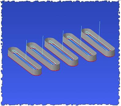
Example
-
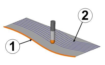
The curve (1) is the leading geometry. All cuts (2) are being creates parallel to the curve.
-
The animation shows the pattern. Note that the toolpath starts at the opposite side of the curve.
The Multiaxis Wizard
Related Topics
How to Create a Multiaxis Parallel to Multiple Curves Feature