Swarf Machining
Introduction
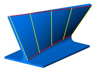
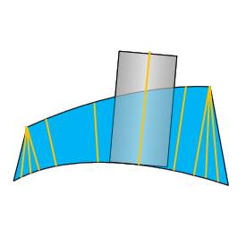
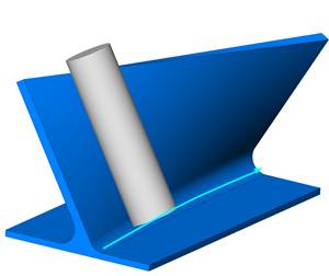
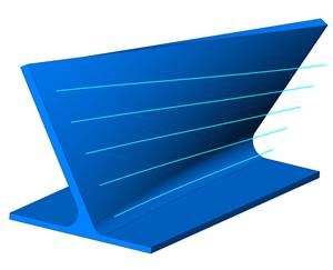
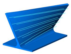
The Swarf feature, also called flank milling, is helpful for machining fluid parts such as impellers or bladed disks (blisks). This toolpath can be used for any type of operation in which you want to cut using the entire length of the tool flute. The goal of swarf milling is to produce the target surface with one cut. The feature geometry requires either a Swarf Surface and/or an Upper Curve and Lower Curve, based on the strategy used. When selecting Swarf Surfaces, you can omit the Upper and Lower Curve. When not selecting the Swarf Surfaces, you must select the Upper and Lower Curves. You can also select all three.

Swarf Parameters
| ... |
Machining direction dialog - selecting the ellipses button brings opens the Machining direction dialog. |
- Top - Machines the part from (0,0,1) Z direction.
-
Other direction - Machines the part from user defined direction (1,0,0)
Geometry Selection
This section provides all of the potential geometry selections for Swarf milling. The available options change slightly depending on the Advanced Control Strategy that is selected.
Note: For all of the following geometry selections,
you select the check box next to the name of the geometry item to include
the item in the toolpath calculation. If the check box is not selected,
then the geometry item is not used to compute the toolpath. After selecting the check box of the geometry
item, click ![]() to enable
selection mode and select the appropriate geometry from the graphics area.
If you turn on a geometry item but do not select geometry, an error message
displays when you compute the toolpath.
to enable
selection mode and select the appropriate geometry from the graphics area.
If you turn on a geometry item but do not select geometry, an error message
displays when you compute the toolpath.
-
Swarf surfaces - are the target surfaces for the feature. This is the geometry that you want the entire flute length of the tool to cut along. Only the Automatic strategy requires Swarf surfaces selection, but they can be selected for any strategy. These surfaces are used when applying a Swarf Offset (stock to leave) unless the Upper Curve and Lower Curve are selected. In this case the curves are used to create the offset.
-
Floor surfaces - are generally below the swarf surfaces and can be selected when you need to avoid cutting the floor or when you want to apply an allowance (Floor clearance) to the floor surfaces. When you turn on Floor Surfaces, the system tries to project (drop) the tool past the swarf surface down to the floor.
-
Tilt lines - can be selected to define the orientation of the tool along the cut. Tilt lines are only used with the Sync with Tilt Lines strategy.
-
Guide Curves
You can select the Guide Curves check box to turn on the ability to select guide curve geometry.
-
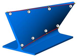
Upper - is the upper edge curve of the feature which is used to define the upper point for the tool orientation and is used when applying a Swarf Offset. Generally, this is the upper edge of the Swarf surfaces.
-
Lower - is the lower edge curve of the feature which is used to define the lower point for the tool orientation and is used when applying a Swarf Offset. Generally, this should be the lower edge of the Swarf surfaces. The chain direction (Start Point) of the lower curve can be used to set the cutting direction and cutting side of the feature.
-
Swap
The swap check box is used to exchange the upper and lower curves for the toolpath calculation. The upper curve is applied as the lower curve and the lower curve is applied as the upper curve. This can be helpful when using the Automatic Strategy and selecting only Swarf Surfaces. This is provided in the event the software detects the curves incorrectly.
-
Swarf Clearance - is used to set an allowance to define how close to cut to the swarf surfaces. You don't have to select Swarf surfaces in order to apply an offset. The offset is applied using the Upper Curve and Lower Curve geometry.
-
Floor clearance - is used to apply an allowance to define how close to cut to the floor surfaces. You must select Floor Surfaces to apply a floor clearance. Negative values are not supported.
Proper Geometry Selections
When using the Automatic strategy, you must select a Swarf Surface. The Swarf Surfaces are not required for any other strategy, but can still be selected. When using any strategy other than Automatic, you can choose to select either Swarf Surfaces or the Upper and Lower Curve. All other selections are explained next.
-
For Sync with Tilt Lines, you must also select tilt line geometry to define the tool orientation along the feature.
-
If you use Sync with Main Direction and select Line, then you must select a line to define the direction. (This is not the same as the tilt line geometry and is only selected in the wizard.)
-
The Floor surfaces are optional for all strategies, and should be used when needed based on the feature.
Tip: The software attempts to automatically detect the upper and lower curves from the selected swarf surfaces. Selecting the Upper Curve and Lower Curve may help improve or speed up the toolpath calculation for complicated or open part geometries.
Machining
-
Side - Select one of the following options to control which side of the part is cut. These options are used together with the Direction parameter.
-
Left - cuts on the left side of the part for open features.
-
Right - cuts on the right side of the part for open features.
-
Inside - cuts the inside of a closed contour.
-
Outside - cuts the outside of a closed contour.
-
Auto-detect - select this option to allow the system to attempt to set the proper machining side of the part using the geometry selections. This works best when the whole part is selected, the swarf surfaces form a closed boundary, or the top and bottom surfaces are aligned horizontally.
-
Surface Normals - uses the surface normal of the feature geometry to define the cutting side.
The following options are only used with the One Way cutting method. (The feature uses one-way cutting unless the Depth Steps (on the Multi Cuts tab) are set to greater than one and then Zig Zag is selected. The following options are no longer available when using Zig Zag.)
-
Climb - cuts the part using climb milling.
-
Conventional - cuts the part using conventional milling
-
Follow lower curve chaining - causes the toolpath to follow the chain direction of the lower edge curves. The chain direction (Start Point) of the lower edge curve is modified using the Lower Curve item of the feature in the CAM Tree.
-
Guide Tool At
You can select whether the software guides the toolpath using the Upper Curve or Lower Curve of the swarf surface. This may be helpful when the upper and lower curve are very different in shape. You can select the curve that creates a better toolpath for your preferences.
Start Point
-
Type - swarf milling uses two start points that are set in one of three ways. The start point of the lower curve is for the tool tip position and the start point of the upper curve is for the tool axis orientation.
-
Exact - the actual start point of the upper and lower curve are used as the start points.
-
Automatic - the system sets the start points.
-
2 points - when selected, click
 to open
the Limit
cuts between two points dialog box. You can type coordinate
values, or click
for each point to select geometry.
to open
the Limit
cuts between two points dialog box. You can type coordinate
values, or click
for each point to select geometry. -
Tilt Line - select this options to define a tilt line as the start point. Click
to open the Pick a Line dialog box. You can type coordinate values,
or click Pick to select geometry. -
Point - defines the start point using a single point. Click
to open the Point dialog
box. You can type coordinate values, or click Pick to select geometry.
Surface Quality
-
Cut Tolerance - defines how accurate the toolpath is in relation to the selected geometry.
Tip: You can reduce the cut tolerance value, for example from 0.0005 to 0.005, to speed up the toolpath calculation while creating and modifying your toolpath. Once your are happy with the result, you can then set it back to the original tolerance to calculate the toolpath before posting the output.
-
Maximum Distance - is the greatest possible distance between two toolpath points that are used to calculate the toolpath. Increasing this value uses less points to calculate the toolpath and decreasing this value uses more points along the geometry to create the toolpath. To change the value, select the check box and type the maximum distance between points.
Advanced Control
Strategy - select from one of the following swarf milling strategies.
-
Sync with tilt lines - select this option when using tilt lines between the upper and lower curves along the surface. You must select the tilt lines used.
-
Sync with (upper/lower) curves - select this option when using the upper and lower curve. Each curve is split into equal distances and the points are used for the tool alignment. This is a commonly used strategy that works best when the shape and length of the upper and lower curves are similar.
-
Sync with main direction - select this option when using an axis. Select from: X-axis, Y-axis, Z-axis, or Line. When Line is selected, click
to open the Pick a Line dialog box. You can type coordinate values,
or click Pick to select geometry.
-
Automatic - select this option to have the system attempt to find a solution where the tool contacts the surface in a line. A Swarf surface must be selected. It is suggested to use the Outside, Inside, or Surface Normals option for the Machining Side parameter when using this option.
-
Shortest Distance - select this option to allow the system to define the tool orientation using the shortest distance between the upper and lower curves. This strategy is helpful when machining flat surfaces with sharp corners.
-
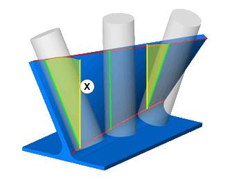
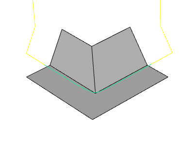
Fanning Distance - for use only with the Shortest Distance strategy, this is the distance from the intersection of two surfaces. Within this distance, the tool axis orientation begins to tilt. This helps to avoid sudden tool axis orientation changes.
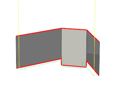
The following example shows fanning with
a value of zero. When the top of the tool reaches the corner it stops
while the bottom of the tool continues to fan around the corner. This
is a result of the upper and lower curve not having the same length. ![]() View Fanning Distance at Zero
View Fanning Distance at Zero
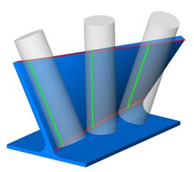
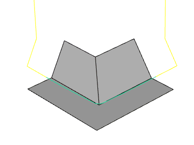
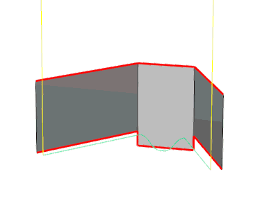
The
following example shows the fanning distance set to a larger value to
cause the tool to more smoothly through the corner. ![]() View Large
Fanning Distance
View Large
Fanning Distance
-
Normal to guide curve - The tool axis is oriented normal to the guide curve.
- Sync with ISO curves - This parameter allows you to follow the ISO curves of the selected nurbs machining surface.
Extensions
The Extensions group provides the ability to extend the toolpath at the start and/or end of the toolpath in addition to any leads that are defined. You can also define a starting angle for the tool orientation at the beginning of the toolpath.
- Type - can be one of
three options:
- Automatic - Extends the front and rear of the rail curve tangentially by the specified distances. On a closed part, the extensions revolve along the toolpath.
- Align to Edges - The start and end of the toolpath are extended by the given distances. The tool axis is aligned to the edges of the surfaces.
- Start/End with angle - The tool axis is aligned to the edges and an additional angle is added to the initial tilting at the start, and the final tilting at the end of the surface edge.
Tool Axis Control
General
-
Maximum Angle Step - defines the maximum allowed angle change between two consecutive tool positions (points) along the toolpath.
-
Minimize Rotation Axis Changes
![]() Select the check box to help reduce heavy machine movements created by
pole singularity.
Select the check box to help reduce heavy machine movements created by
pole singularity.
![]() Clear the check box to turn off this option.
Clear the check box to turn off this option.
Gouge Check
Gouge and Excess
The Gouge and Excess options provide you with the ability to completely degouge the swarf path, or you can balance the amount of gouging to the target geometry, for example, for curved surfaces that can't be swarf machined. You can use these options with one or both of Swarf Surfaces and Additional Check Surfaces. There is also an option to gouge check using only the guide curves.
Check
Select one of the following options to gouge check the swarf toolpath.
-
Guide Curves Only - automatically creates a gouge check for the tool against the upper and lower curves. (No other settings are available when selecting this option.
Note: The following options provide further control over the gouge check with the Collision Handling settings.
-
Swarf Surfaces - applies the Collision Handling setting to the swarf surfaces.
-
Additional Surfaces - allows you to select surfaces other than the swarf surface to which the Collision Handling setting applies. Click
 to enable selection
mode, and select the additional surfaces geometry.
to enable selection
mode, and select the additional surfaces geometry. -
Swarf and Additional Surfaces - allows you to apply the Collision Handling settings to both the swarf surfaces and any additional surfaces you select. Click
to enable selection mode,
and select the additional surfaces geometry.
Collision Handling
The Collision Handling settings provide the following three options.
-
Degouge - removes any gouging from the toolpath by moving the tool out away from the surface (or at a right angle to the plane of the upper and lower curve), using a Gouge Allowance which is a tolerance to the target geometry.


-
Balance - partially moves to the tool out of gouging by moving the tool out away from the surface. If you compared a pre-gouge checking toolpath with the same toolpath after removing all gouging, balance creates the toolpath in the middle of the two paths. This leaves an equal amount of gouging and rest material compared to the target geometry.

-
Balance Within Allowance - is similar to balance, but allows you to specify the exact amount of allowable gouging using the Gouging Allowance and the Excess Material Allowance.
Note: The following settings become available when selecting Degouge or Balance with Allowance.
-
Gouge Allowance - is the amount of gouging that you want to allow when using gouge checking options. (This is not available for Balance.)
-
Excess Material Allowance - defines how much rest material is allowed when performing the gouge checking calculation. This is only available with Balance Within Allowance. If you don't know an exact value, you can set this value large and then define the exact amount of gouging using the Gouge Allowance.
Avoid by Relinking
The Avoid by Relinking option allows you to remove gouging toolpath by retracting and linking the gouging toolpath using the current linking options. This can be applied to the Swarf Surfaces and/or Additional Check Surfaces.
Check
-
Swarf Surfaces - applies a retract and link move to any gouges found on the swarf surfaces.
-
Additional Surfaces - allows you to select surfaces other than the swarf surface to which the retract and link move applies. Click
to enable selection mode,
and select the additional surfaces geometry. -
Swarf and Additional Surfaces - allows you to apply the retract and link move to both the swarf surfaces and any additional surfaces you select. Click
to
enable selection mode, and select the additional surfaces geometry.
-
Check Faces Clearance - determines the amount of clearance around the selected gouge check surfaces.

Avoid by Retracting
The Avoid by Retracting option allows you to remove gouging toolpath by retracting the tool just enough to remove the gouging portion. This can be applied to the Swarf Surfaces and/or Additional Check Surfaces.
Check
-
Swarf Surfaces - applies a retract move to any gouges found on the swarf surfaces.
-
Additional Surfaces - allows you to select surfaces other than the swarf surface to which the retract move applies. Click
to enable selection mode, and select the additional surfaces geometry. -
Swarf and Additional Surfaces - allows you to apply the retract move to both the swarf surfaces and any additional surfaces you select. Click
to enable selection
mode, and select the additional surfaces geometry.
-
Check Faces Clearance - determines the amount of clearance for the selected gouge check surfaces.

Clearance
These values are used to define the desired clearance distance around the tool Shaft, Holder, and Arbor.
Link
To learn about the Link parameters, view the Multiaxis Links.
Multi Cuts
Pattern Slices
-
Depth Steps
-
By Slice Distance - defines the depth step using a distance value. The Direction setting becomes available.
-
By Number of Slices - defines the depth step using a number of slices.
|
|
|
Single Slice |
Multiple Slices |
-
Pattern
-
Morph - creates an offset from the upper and lower curve that are blended together (morphed).
-
Steps From Top - creates the slices parallel to the upper curve.
-
Steps From Bottom - creates the slices parallel to the lower curve.
-
Direction - is only available whenBy Slice Distance is selected.
-
Along Tool Axis - the tool retracts along the tool axis for non-tapered tools.
-
Along Contact Line - the tool retracts along the tool contact line for tapered tools.
-
Follow Surface Topology - the tool retracts using the shape of the geometry to determine the best retract direction.
- Cut from bottom
 With this check box cleared, the cuts will be made from the top, down.
  With this check box selected, the cuts will be made from the bottom, up.
Tool Guidance
-
Toolpath Damping
Toolpath damping smooths out abrupt tool movements along the feature. This is designed to handle sharp changes (corners) in the lower curve of the swarf feature that cause the tool to quickly plunge (or retract). When select the User Defined option, the Damp value becomes available. The Damp value range is 0 through 999. A value of zero means the tool diameter is used to create the damping. If you specify any other value, that value is used to create the damping and the tool diameter is ignored. The value is a range from the lower curve in which the tool can move to create a smoother transition between the sharp corners.
-
Tool Shift - modifies the tool-to-surface contact point of the tool. Select one of the two following options.
-
Constant for each slice - when selected, only the To value is available. Type the amount of axial shift added for all toolpath slices in the To box.
-
Gradual for each slice - type the amount of axial shift for the beginning of the toolpath in the From box. Type the amount of axial shift for the end of the toolpath in the To box. These values are used to slowly change the axial shift during the toolpath. In the middle of the toolpath, the axial shift is fifty percent of the difference between the To and From boxes.
-
To - is the axial shift value used at the end of the toolpath or for constant shifts.
-
From - is the axial shift value used at the beginning of the toolpath for gradual shifts.
Note: Positive values cause the tool to retract and negative values cause the tool to plunge (or infeed).
Pattern Layers
-
Number of Layers - type the desired number of layers or passes applied to the part.
-
Layer Distance - type the distance between each layer, that can be considered the depth of cut/step over. This is only available when the Number of Layers is greater than one.
|
|
|
|
Single Layer |
Two Layers |
Sorting
- Machine by - These options define how different zones, created by gaps along the selected drive surfaces, are to be handled.
- Lanes - move past the gap to continue the cut in the next zone.
- Regions - stops at the gap to handle the cuts in the current zone first.
| Machine by : Lanes | Machine by : Regions |

|

|
- Sequence - the following option are only available when the Number of Layers
is set to more than one.
- By Layer - all slices of one pass are cut before moving on to the next pass.
- By
Slice - the first slice of each pass is cut before moving
on to the next slice.
- Method -
- One Way - the toolpath only cuts in one direction across the part with a retract move at the end of each slice.
- Zig Zag - the toolpath alternates cutting direction across the part, eliminating the need for retract moves. This option is only available when the slices or layers are set to more than one.
- Spiral - The spiral option generates spiral cuts on the drive surface. The spiral only works with closed contours, and when using multiple cuts with a Morph Pattern, and Sorting of Machine by Regions. The existing cuts are transformed into a spiral motion. The result is one long spiral toolpath without any link motions, per surface.
Transform/Rotate
To learn about the transform/rotate settings, view Transform/Rotate.
Mirror
To learn about the mirror settings, view Mirror.
Corners
Inside Corners
-
Sharp Corner - creates sharp corners using orthogonal linear moves.
-
Round Corner - creates round corners using an arc move.
-
Radius - defines the radius used for the round corner.
-
Detection Angle - is the angle value used to detect corners to apply a round corner.
-
Relief Curve - cuts into the corner based on the length and detection angle settings.
-
Length - is a distance the tool travels into the corner.
-
Detection Angle - is the angle value used to detect corners for the relief curve.
Outside Corners
-
Roll Around - handles corners using an arc move.
-
Sharp Corner - creates sharp corners using orthogonal linear moves.
-
Detection Angle - is the angle value used to detect corners to apply a sharp corner.
-
Loop - creates a loop move at each corner using the radius and detection angle settings.
-
Radius - is the radius of the loop move.
-
Detection Angle - is the angle value used to detect corners for the loop.
Utility
Feedrate Control
The following two options are used with the Adjust Feedrate parameters to modify the feedrate for one or all of three specific cutting scenarios as explained.
- Minimum Feedrate (%) - determines the minimum cutting feedrate for the feature when using any of the Adjust Feedrate options.
- Maximum Feedrate (%) - determines the maximum cutting feedrate for the feature when using any of the Adjust Feedrate options.
- Adjust Feedrate on Edges
![]() Select the check box to adjust the feedrate of the tool as it moves around
inside or outside corners of the model. For example, the feedrate is at
maximum along a straight cut, but then slows down when the tool reaches
the corner. The smaller the radius of the corner, the more the feedrate
is reduced, based on the maximum and minimum feedrate settings.
Select the check box to adjust the feedrate of the tool as it moves around
inside or outside corners of the model. For example, the feedrate is at
maximum along a straight cut, but then slows down when the tool reaches
the corner. The smaller the radius of the corner, the more the feedrate
is reduced, based on the maximum and minimum feedrate settings.
![]() Clear the check box to use a constant feedrate for the feature.
Clear the check box to use a constant feedrate for the feature.
Important: This option doesn't change the feedrate for outside corners when the Outside Corners option is set to Roll Around. You must select either Sharp Corner or Loop. When Loop is used, the feedrate is reduced for the corner and the loop move. (These options are found in the Corners tab of the wizard.)
- Adjust Feedrate for Fanning
![]() Select the check box to adjust the feedrate of the tool in fanning situations
using the maximum and minimum feedrate settings. For example, when the
tool cuts a corner where the upper curve and lower curve are not the same
distance, the tool tip must move faster or slower than the tool flute
at the upper curve (depending on the feature). This allows the software
to calculate the feedrate at the tool flute/upper curve instead of only
at the tool tip.
Select the check box to adjust the feedrate of the tool in fanning situations
using the maximum and minimum feedrate settings. For example, when the
tool cuts a corner where the upper curve and lower curve are not the same
distance, the tool tip must move faster or slower than the tool flute
at the upper curve (depending on the feature). This allows the software
to calculate the feedrate at the tool flute/upper curve instead of only
at the tool tip.
![]() Clear the check box to use constant feedrate for the feature.
Clear the check box to use constant feedrate for the feature.
- Adjust Feedrate for Cutting Depth
![]() Select the check box to adjust the feedrate of the tool based on the depth
of cut (along the tool flute) using the maximum and minimum feedrate settings.
This means that the feedrate can be increased when less of the flute is
cutting, and decreased when more of the tool flute is cutting material.
Select the check box to adjust the feedrate of the tool based on the depth
of cut (along the tool flute) using the maximum and minimum feedrate settings.
This means that the feedrate can be increased when less of the flute is
cutting, and decreased when more of the tool flute is cutting material.
![]() Clear the check box to use a constant feedrate for the feature.
Clear the check box to use a constant feedrate for the feature.
- Use rapid
feedrate
Select the check box to use rapid feedrate and type the desired
rapid feedrate value in the box.Clear the check box to turn off rapid feedrate.
Retract moves, for example, now use the standard feedrate.
Markers
to learn about the Markers settings, view Markers (Utility Tab topic).
Miscellaneous
- Max. Angle Step for Rotation Axis
This option determines the maximum angle step, or amount or rotation, applied to rotation axis movements between toolpath points. Select the check box to turn on the option and then type the angle value in the box. Any machine movement beyond this angle is reduced by adding more toolpath points to smoothen the machine movements as a division of the angle change and maximum angle step. This is provided to reduce or eliminate abrupt machine movements, specifically for some machine controllers that do not limit large rotation changes, which can break tools or gouge surfaces.