How to Vectorize Using the Multi-Color Strategy
Introduction
This topic explains how to vectorize an image using BobART. The use of the Multi-Color Strategy is the main focus, but the Black and White strategy is also examined. Many useful tips and a few different approaches are provided.
Example File
The part file for this tutorial is available for download at: http://www.bobcad.com/helpfiles. If you are connected to the Internet, you can click the link provided to download and save the Multi-ColorVectorization Example 1.bbcd zip file. After downloading the zip file, extract the files on your system in a place that is easy to remember. You can then open the BobCAD file (.bbcd) to use with this tutorial.
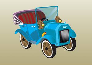
In this example, a color image of a car is used to create vector geometry. The image used is shown next.
Part 1) Open the Example File
-
In the Quick Access Toolbar, click
 Open.
Open. -
In the Open dialog, select the folder in which you saved the example files.
-
Select Multi-Color Vectorization Example 1.bbcd, and click Open.
The file is opened (the graphics area is empty).
Part 2) Load the Image
-
In the BobART tree, right-click
 Images, and click Load
Image.
Images, and click Load
Image. -
In the Open dialog, select the folder in which you saved the example files.
-
At the bottom of the dialog, next to Files of Type, click the arrow and select All Files (at the bottom of the list).
-
Select Old Car.bmp, and click Open.
The image is loaded and displayed in the graphics area.
Notice the ![]() Image-Old Car item is added to the BobART tree under
Image-Old Car item is added to the BobART tree under ![]() Images.
Images.
Part 3) Hiding and Showing the Image
When vectorizing images, you need to hide and show the image in order to view and work with the geometry that is created. There are two ways to hide images, and it is important to understand how they work.
-
Click anywhere in the graphics area (to give it key focus), and press I.
The letter I is the keyboard shortcut to hide all images.
Press I again and the image is shown.
Remember, this method is used to hide all images in the graphics area. -
In the BobART tree, right-click
 Image-Old Car, and click Blank/Unblank.
The image is hidden. This method is used to hide or show a single image. -
Right-click
Image-Old
Car, and click Blank/Unblank.
The image is shown. (If you do not see the image, click anywhere in the graphics area, and press I.)
Note: For the remainder of this tutorial, when you are instructed to Hide or Show the image, use the method that you prefer.
Part 4) Using the Raster to Vector dialog
This section explains how the Raster to Vector dialog is used to create and modify the vectorized geometry.
-
In the BobART tree, right-click
Image-Old Car, and click Vectorize.
The Raster to Vector dialog is displayed. -
In the Vectorize Strategy group, click Multi-Color Strategy.
Under the color boxes, click Check All.
To close the dialog and create geometry, click OK. -
Hide the image to view the geometry.

The image is processed using all 64 colors to create the vectorized geometry. Notice the horizontal lines. This is a result of the gradient in the background of the image. The vectorization separated the gradient into six unique colors.
Although it is not the method used for this tutorial, you could decide that you are now done with the vectorization and simply edit the geometry. Depending on what you want to achieve, this may not be the most efficient method to use. -
Next to
Image-Old Car,
click  to expand the tree item.
To edit the parameters, right-click Vectorization,
and click Edit.
Vectorization,
and click Edit.
Note: You can also right-click Image-Old Car, and click Vectorize.
-
In the Raster to Vector dialog, click Uncheck All.
Click to select the four check boxes in the top row of Colors to be Vectorized.
In the first column, select the seventh check box from the top.

Click OK.
Notice that the geometry from the first vectorization is removed and replaced with new geometry.

When there is geometry that you want to keep, you copy it to a new layer. This allows you to vectorize the image more than once (in order to be more precise).
Part 5) Copy Geometry to a New Layer to Save It
-
Right-click anywhere in the graphics area, and click Select.
The geometry that you select contains some double entities. You use chain-selection to avoid selecting the unwanted geometry.
Press and hold Shift, and click to chain-select the profile of the grill area as shown next.

Inside of the profile you just selected, press and hold Shift, and click each closed loop one time until they are all selected.

Notice in the previous image that double entities can make it appear that a complete loop is not selected, even though it is. You confirm the selections in step 5 -
Press Ctrl+C to copy the entities.
-
In the Layers Manager, right-click the layer name Grill and select Active Layer.
Confirm that the Active Layer icon is displayed
next to Grill.
Active Layer icon is displayed
next to Grill.
This sets the layer to the active drawing layer. -
Press Ctrl+V to paste the entities onto the active layer.
-
In the Layers window, right-click anywhere, and click Hide All Layers.
Right-click the layer name Grill, and click Show Layer.
-
Now that the geometry selection is confirmed to be correct, right-click in the Layers window, and click Hide All Layers.
Double-click the layer name CAD, and confirm that it is set as the active layer ().
Right-click the layer name CAD, and click Show Layer.
It is important that only the CAD layer is visible (for the process that we are using).
This assures that you are only seeing the results of the vectorization and not the copied geometry. -
To cancel selection mode, right-click anywhere in the graphics area, and click Cancel.
Tip: You can also press Esc to cancel selection mode.
Part 6) Use the Black and White Strategy
For this part, you experiment with the Black and White strategy to get the profile of the car.
-
In the BobART tree, right-click
Vectorization and click Edit. -
Select 2-Level (Black/White) Strategy.
-
In the Threshold Value box, select the text, and type 40.
Select the text again, and type 60.
Notice the preview of the image is updated each time that you change the value.
You can also click and drag the Threshold Value slider, in small increments, and release to accomplish the same thing.
Set the Threshold Value to 174.
Click OK.
-
In the document toolbar, click
 to enable selection mode.
Press and hold Shift, and click to chain-select the profile of the car as shown next.

-
Press Ctrl+C to Copy.
-
In the Layers Manager, right-click the Profile layer, and select Active Layer.
Confirm that theActive Layer icon is displayed
next to Profile.
This sets the layer to the active drawing layer.
Pres Ctrl+V to Paste.
To confirm the geometry is properly pasted, right-click anywhere in the Layers window, and click Hide All Layers.
Right-click the layer name Profile, and click Show Layer.
The geometry should appear as follows.
-
Right-click the layer Profile, and click Hide Layer.
Double-click the CAD
layer, and confirm that it is set to the active layer (![]() ).
).
Right-click the CAD layer, and click Show Layer. It is important that only the CAD layer is visible.
Press Esc to cancel selection mode.
Part 7) Continue Using the Multi-Color Strategy
-
Right-click
Vectorization,
and click Edit. -
Select Multi-Color Strategy.
-
Click the # of Colors arrow, and click 32.
Notice that the preview of the image changes based on the # of Colors selected.
When you change the number of colors, the image is actually reduced to the selected number of colors, and the color check boxes are also updated under Colors to be Vectorized.
Repeat this process of reducing the # of Colors (for example to 16, then 8, then 4, etc.) and observing the image preview.
This process is very helpful when trying to vectorize only a certain area of the image. -
Set the # of Colors to 24.
Click Uncheck All.
Click to select the top check box in column 2 of Colors to be Vectorized.
Click OK.
-
When you zoom-in to view the front wheel, you can see that there are small unwanted entities as shown next.

Part 8) Remove Chains Less Than
-
Right-click Vectorization, and click Edit.
In the Vectorize Parameters group, in the Remove Chains Less Than box, type 75.
Click OK.
Notice that the unwanted chains are removed.
This parameter is an important tool for vectorization.
-
In the document toolbar, click
to enable selection mode.
In the graphics area, click and drag a window around the three wheels as shown next.

-
Copy the selected geometry, and paste it to the Wheels layer. (Use either method as explained earlier.)
-
Check that the geometry is properly pasted to the new layer as explained earlier.
-
Set the CAD layer as the active layer (
).
Make sure that only the CAD layer is visible.
Note: To get
the other contours from the wheel, the following color is used.
The Remove Chains Less Than value was changed to
100, to create the following result.
Be sure to reduce the Remove Chains Less Than value
(if needed) when moving on to vectorize a new area of the image.
Part 9) Edit the Vectorization Parameters
In this part, the seat is the target area from which you create geometry.
-
Right-click Vectorization, and click Edit.
-
Change the # of Colors to 20.
Select the following colors.
In the Remove Chains Less Than box, type 100.
Click OK.
The result appears as though some of the geometry is missing from the seat. To confirm if this is correct, show the image, and compare the image and the geometry. You may want to hide and show the image a few times as you examine certain areas. You can see that the geometry from the seat is accurate (the steering wheel and the windshield cause the missing areas.)
You could window select the (seat) geometry and copy it to a new layer, but you would get double entities that need to be cleaned up later. In the following steps, you edit the vectorization and get the seat geometry in two steps. This again helps you to get clean geometry that requires less editing later. -
Edit the parameters, and click to clear the top check box of the second column.

Click OK.
You can see that now you have much cleaner results.
Show and hide the image a few times to compare the image and the geometry.
The result is grabbing mostly the brown areas of the seat. -
Use chain-selection to select the desired geometry, and copy it to the Seat Browns layer.


The red areas of the seat are copied to the Seat Reds layer.
Edit the parameters, and select the following colors.
Click OK.
This time mostly the red areas of the seat are vectorized.
Show and hide the image to compare. -
Copy the desired geometry (remember to use the chain-selection method), and paste it to the Seat Reds layer.

The brown areas of the seat are copied to the Seat Browns layer.
All of the geometry created so far is shown next.
-
Continue this process until you have created all of the desired geometry from the image.
(Pick a target area. Adjust the Number of Colors to create the desired results. Copy the geometry to a new layer, and repeat.)

Final Notes
Image Origin
You can change the location of the image in the graphics area using the Image Origin dialog.
To change the image location:
- Right-click Image-name, and click Change Origin.
- Set the Origin values (in relation to the WCS or world coordinate system). The Origin of the image is the lower-left corner.
- Click OK. The image is moved.
- To move any vectorized geometry to the new location, open the Raster to Vector dialog, and click OK.
Moving the image is helpful when you vectorize more than one image.
Image Size
In the Raster to Vector dialog, the Image Size values are used to scale the vectorized geometry that is created. (The size of the image is not actually changed.)
Remove Arcs
If you want to create the vector geometry using only line segments,
clear the ![]() With Arcs check box in the Raster to Vector
dialog.
With Arcs check box in the Raster to Vector
dialog.
Vectorize Parameters - Accuracy
The Accuracy parameter can be changed to create smoother or rougher contours.
Low Accuracy (0.10 pixels)

High Accuracy (0.90 pixels)

This concludes the tutorial.