How to Create a Multiaxis Cuts Along Curve Feature
Introduction
This tutorial explains how to create a Multiaxis feature with the Cuts Along Curve toolpath. This feature requires the selection of a Lead Curve, which is used to create the toolpath. The toolpath slices are created at a right angle to Lead Curve and applied to the second required selection, the Drive Surface. The Lead Curve can be on the surface, a surface edge, or you can assign wireframe geometry as shown in this tutorial. (If the Lead Curve creates intersecting toolpath segments, then the calculation will fail, and the curve must be recreated.)
Example File
The BobCAD part file for this tutorial is available for download at: http://bobcad.com/helpfiles. If you are connected to the Internet, you can click the link provided to download and save the Cuts Along Curve Example 1 BBCD.zip file. After extracting the zip file, you can open the file to follow along with this example. In the example file provided, the stock and Machine Setup are already defined for the part. The part is simulated using the BC Table-Table machine.
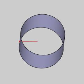
In this example, you create a toolpath to machine the outside of a cylinder. Instead of using a solid model, a surface (zero thickness) is used to show how the surface normal direction can be changed to cut the opposite side of the surface. This action is then applied to this example to machine the inside of the cylinder.
Part 1) Add the Feature
-
In the CAM Tree Manager, right-click
 Machine
Setup and click Mill Multiaxis.
Machine
Setup and click Mill Multiaxis. -
In the Multiaxis Wizard, click Surface and click Cuts Along Curve.
-
Click Next>> to go to the Posting settings.
Part 2) Define the Posting Parameters
-
The Work Offset # is automatically set to the value defined in the Machine Setup.
You can change the value here to update the Work Offset # for the feature. -
Click Next>> to go to the Multiaxis Posting settings.
Part 3) Define the Multiaxis Posting Parameters
-
Notice, at the top of the dialog box, that the Use Machine Settings check box is selected.
This means that the Multiaxis Posting parameters for the feature use the same parameters as the machine that is selected in Current Settings.
You can clear the Use Machine Settings check box to define the Multiaxis Posting parameters of the feature separately from the current machine settings.
An example usage is explained later. -
Click Next>> to go to the Tool settings.
Part 4) Define the Tool Parameters
-
In the Tool Data group, click to clear the
 System
Tool check box.
System
Tool check box. -
Set the Diameter to 0.500 and the Flute Length to 3.000.
-
Set the Corner Radius to 0.250 and the Overall Length to 5.000.
-
Click Next>> to go to the Parameters.
Part 5) Select Geometry
-
To define the lead curve, in the Surface Paths tab under Pattern, click Lead.
-
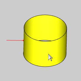
Click to select the line (leading curve).
The toolpath for the feature is created normal (at a right-angle) to the curve.

-
To confirm the selection, click
 .
. -
Click Drive Surfaces, and click the cylindrical surface.
The Drive Surfaces are the geometry to which the toolpath is applied.

-
To confirm the selection, click
.
Part 6) Define the Parameters and Compute the Toolpath
-
To leave stock material for a finish operation, in the Drive Surface Offset box, type 0.030.
-
Under Area next to Type, click the down arrow and select Full, Start and End at Exact Curve End Points.
Notice by the name, that this parameter is in reference to the Lead Curve, and not the Drive Surface as is the case for the other surface toolpaths. Any part of the Lead Curve that can't be projected onto the surface is not used. So, for this example, this causes the first toolpath slice to start at the exact surface edge, or rather the exact curve end points. -
In the Sorting group, next to Cutting Method, select Spiral.
-
In the Stepover group, set the Maximum Stepover to 0.250 (A large stepover is used to better show the toolpath).
-
At the top of the dialog box, click the Link tab.
Click Retracts. -
Under Clearance Area next to Type, click the down arrow and select Cylinder.
Confirm the Radius value is 3.00.
Next to Direction, confirm that Z Axis is selected.
Click OK. -
To create the toolpath, at the bottom of the wizard, click Compute.
Notice the direction of the toolpath. It is perpendicular to the Lead Curve.

The following image shows the result with a Lead Curve that is diagonal to the cylinder.

Part 7) Curve Chain Direction
The chain direction of the selected curve is used to define the start and end of the toolpath. For example, this part is currently cutting from the bottom of the part to the top.
-
In the CAM Tree under
 Multiaxis, click
  to expand the
  Geometry
folder.
Geometry
folder.
Right-click Lead
Curve and click Modify Start
Point.
Lead
Curve and click Modify Start
Point. -
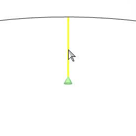
When you zoom-in to view the chain direction (the chain end-point is shown), you can see that it is starting at the bottom and ending at the top of the cylinder.
-
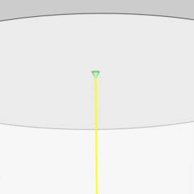
To change the chain direction, rotate the part and click near the bottom of the line (curve).
-
The chain direction is now from the top of the cylinder to the bottom.
-
To confirm the selection, click
.
(Alternatively, right-click Lead Curve and click Reverse Direction to flip the chain direction.) -
In the CAM Tree, right click
 FeatureMultiaxis,
and click Compute All Toolpath.
FeatureMultiaxis,
and click Compute All Toolpath.

The toolpath now starts at the top of the cylinder.
Part 8) Simulation
-
In the quick access toolbar, of the CAM Tree Manager, click
 .
. -
During simulation, you can see that the tool is cutting on the outside of the cylinder.

-
To close simulation, click
 Exit Simulation.
For more help using simulation, view Getting Started with Simulation.
Adjust the Machine Table Rotation
When you simulate the program, the machine table is sometimes rotated in a way that doesn't allow you to view the part without rotating the view of the machine. You can change the Angle Pair settings for the feature to modify the table rotation used in simulation and in the posted code.
-
In the CAM Tree, right-click
Feature Multiaxis,
and click Edit. -
Click Multiaxis Posting in the tree.
Clear the Use Machine Settings check box.
In the Angle Pair group, next to Use, select Other Solution.
When you simulate the program again, you can now view the part being cut from the opposite side of the machine.
The table is rotated to use the other solution to the rotation angles of the primary and secondary rotary axes (angle pair). This changes the posted output of the program as well as the simulation.
Important: You don't have to compute the toolpath to update this setting for simulation, but you must Post the program to update the code if has already been posted.
Part 9) About the Surface Normal
The surface normal of Drive Surfaces must point away from the Drive Surface in order to create the toolpath on the proper side of the surface. For this example, because the geometry used for the part is a surface and not a solid, the surface normal can be used to reverse the machining side of the part. To elaborate, if the cylindrical shell/surface is given a thickness, meaning that there is an outer surface and an inner surface, then there is a normal for each surface. In this case, the outer surface normal must point out, and the inner surface normal must point in. The machining is then applied to the selected surface.
-
in the document toolbar, click
 Surface Normal.
The surface normal is now shown for all surfaces in the graphics area. (You can also press N to hide or show the surface normal.)
-
The next step is to reverse the surface normal to force the tool to cut the inside of the surface.
In the Reverse group, of the Utilities ribbon, click Reverse Surface Normal.
 -
In the graphics area, click the surface.

-
To confirm the selection, click
.
Click Cancel to close the Data Entry Manager, and turn off the surface normal view. -
After modifying the surface normal, we need to reassign our modified Drive Surface geometry.
Under Feature Multiaxis, right-click Drive Surfaces, and click Re/Select.
Click the surface to select it, and click to confirm
the selection. -
Right-click FeatureMultiaxis, and click Compute All Toolpath.
The toolpath is now applied to the inside of the surface.

This is a result of the default tool axis orientation, which uses the surface normal to align the tool. This means that the tool orientation is at a right angle to the surface at any point (perpendicular to the tangent at the contact point.)
The tool axis orientation must be changed.

Part 10) Tool Axis Orientation
-
In the CAM Tree, right-click
FeatureMultiaxis,
and click Edit. -
Click Parameters, and click the Tool Axis Control tab.
-
Next to Tool Axis Will, click the down arrow and select the tilting strategy Tilted Through Point.
-
Below Tilted Through Point, click Tilt Point.
The Pick Point dialog box displays. -
Click Pick to select geometry from the graphics area.
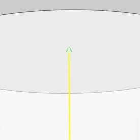
Select the point that is above the cylinder.
Notice that the XYZ values are updated from the selected point (X0 Y0 Z10).
-
Click OK.
Part 11) Clearance Area
Now that the inside of the cylinder is being machined, the Clearance Area is changed to a plane above the part.
-
Click the Link tab, and click Retracts.
-
Under Clearance Area next to Type, click the down arrow and select Plane.
In the Height box, type 5.000.
Click OK. -
To add the changes, click Compute.
Notice that the toolpath moved further away from the surface (this is a result of changing the tool orientation which changed the tool contact point on the surface).
-
In the quick access toolbar, of the CAM Tree Manager, click
.
For more help using simulation, view Getting Started with Simulation.
The toolpath now cuts the inside of the cylinder.
The tool axis orientation is always tilted through the selected point.

This concludes the tutorial.