How to Create a Multiaxis Parallel Cuts Feature
Introduction
This tutorial explains how to create a Multiaxis feature with the Parallel Cuts toolpath. This toolpath creates parallel cuts along a selected surface geometry. Only a Drive Surface selection is required for the feature, which can be one or more surfaces.
Example File
The BobCAD part file for this tutorial is available for download at: http://bobcad.com/helpfiles. If you are connected to the Internet, you can click the link provided to download and save the Parallel Cuts Example 1 BBCD.zip file. After extracting the zip file, you can open the file to follow along with this example. In the example file provided, the stock and Machine Setup are already defined for the part. The part is simulated using the BC Table-Table machine.
In this example, a finishing toolpath strategy is applied to the curved face of the part model. You learn how the surface normal direction defines the tool orientation and how to apply a tilting strategy to change this orientation and resolve a gouge. You also examine how changing the Link parameters modifies the toolpath and tool/machine movement. The last part explains applying a gouge check to the model.

Part 1) Add the Feature
-
In the Data-CAM Tree Manager, click the CAM Tree tab.
-
Right-click
 Machine
Setup and click Mill Multiaxis.
Machine
Setup and click Mill Multiaxis. -
In the Multiaxis Wizard, click Surface, and confirm that Parallel Cuts is selected.
-
Click Next>> to go to the Posting settings.
Part 2) Define the Posting Parameters
-
The Work Offset # is automatically set to the value defined in the Machine Setup.
You can change the value here to update the Work Offset # for the feature. -
Click Next>> to go to the Multiaxis Posting settings.
Part 3) Define the Multiaxis Posting Parameters
-
Notice, at the top of the dialog box, that the Use Machine Settings check box is selected.
This means that the Multiaxis Posting parameters for the feature use the same parameters as the machine that is selected in Current Settings.
You can clear the Use Machine Settings check box to define the Multiaxis Posting parameters of the feature separately from the current machine settings.
An example usage is explained later. -
Click Next>> to go to the Tool settings.
Part 4) Define the Tool Parameters
-
In the Tool Data group, confirm the Diameter is set to 0.500.
-
Change the Corner Radius value to 0.250 so the software searches and loads a matching tool from the Tool Library (System Tool is selected).
-
Click Assign Tool Holder.
-
On the right side of the Milling Tool Holder Library, click to select the 0.5 inch I.D. Arbor CAT 40 holder and click OK.
-
Click Next>> to go to the Parameters.
Part 5) Select Geometry
-
In the Pattern group of the Surface Paths tab, click Drive Surfaces.
Click to select the front face of the model as shown next.
The Drive Surface selection determines where the toolpath is applied.

-
To confirm the selections, click
 .
.
Part 6) Feature Setup
-
In the Pattern group, click Constant Z.
Notice that this sets the Machine Angle in Z parameter to 0 and disables the Machine Angle in XY parameter.
This is used to create toolpath cuts that have a constant Z-axis value. -
Under Sorting, confirm the Cutting Method is set to One Way.
-
At the top of the dialog box, click Link.
Click Retracts.
Confirm that the Direction is set to ZAxis and the Height is set to 4.75.
This value is automatically set from the value defined in the Machine Setup (but only when the feature is created).
You can change the value here to update the Clearance Plane after creating the feature.
Click OK. -
At the bottom of the dialog box, click Compute.

Notice that the toolpath Links are retracting to the Clearance Area between each slice.
You can also see that no lead-in or lead-out is defined.
-
To edit the feature, in the CAM Tree, right-click
 FeatureMultiaxis,
and click Edit.
FeatureMultiaxis,
and click Edit.
Part 7) Edit the Links
-
On the left side of the dialog box, click Parameters.
Click the Link tab. -
In the Entry/Exit group, for First Entry, (on the right side) select Use Lead-In.
To open the Lead-In dialog box, click .
.
Confirm that the Use Default Lead-In check box is selected, and click OK. -
Next to Last Exit, (on the right-side) select Use Lead-Out.
-
To open the Default Lead-In/Out dialog box, at the bottom of the dialog box, click Default Lead-In/Out.
In the Lead-In group, next to Type, select Tangential Line.
Next to Copy, click .
.
Click OK. -
In the Link Between Slice group, set the Large Moves to Retract to Rapid Distance.
(To view the current distance values in the Retracts dialog box, click Retracts.) -
To update the changes, click Compute.


The result shows that the First Entry and Last Exit moves now use a Lead-In and a Lead-Out. Also, instead of the tool retracting to the Clearance Plane at the end of each slice, it now retracts to the Rapid Plane. (These rapid moves are shown in yellow.) You can compare these results to the toolpath result shown earlier. Notice that the yellow rapid moves are in front of the selected drive surface and not above it as it was earlier. This is the difference between Retract to Clearance Area and Retract to Rapid Distance.
Part 8) Simulation
-
In the quick access toolbar, of the CAM Tree Manager, click
 .
.
To learn more about using simulation, view Getting Started with Simulation. -
When you simulate the program, you see that the tool orientation is always the same as the surface normal direction along the surface.

During simulation, you can also see that the part is gouged because of the short tool length. The gouge happens at the end of the toolpath, because there is not enough clearance between the lower surface and the tool holder.

This issue could be resolved by using a longer tool, but maybe you don't have a longer tool to use for the job.
This can be resolved by changing the tilting strategy or using a gouge check as explained later.
-
To close simulation, click
 Exit Simulation.
Adjust the Machine Table Rotation
When you simulate the program, the machine table is sometimes rotated in a way that doesn't allow you to view the part without rotating the view of the machine. You can change the Angle Pair settings for the feature to modify the table rotation used in simulation and in the posted code.
-
To edit the feature, in the CAM Tree, right click
FeatureMultiaxis,
and click Edit. -
Click the Multiaxis Posting icon in the tree.
Clear the Use Machine Settings check box.
In the Angle Pair group, next to Use, select Other Solution.
When you simulate the program again, you can now view the part being cut from the opposite side of the machine.
The table is rotated to use the other solution to the rotation angles of the primary and secondary rotary axes (angle pair). This changes the posted output of the program as well as the simulation.
Tip: You don't have to compute the toolpath to update this setting for simulation, but you must Post the program to update the code if has already been posted.
Part 9) Using Tool Axis Control
In this part of the tutorial, you use the Tool Axis Control tab to tilt the tool orientation away from the bottom surface.
-
Edit the feature, click Parameters, and click the Tool Axis Control tab.
-
Next to Tool Axis Will, the Tilting Strategy is set to Tilted Relative to Cutting Direction.
This tilting strategy uses the surface normal direction to define the tool orientation. In addition to this tool orientation, you can define a lead angle (forward and backward) and a side angle (left or right) based on the direction that the tool is moving. -
To tilt the tool to the right of the toolpath based on the cut direction, in the Tilt Angle at Side of Cutting Direction, type 45.00.
-
Click Compute.
The tool tilting is visible in the toolpath display.
This has caused the rapid movements (links) to move up away from the bottom surface.
-
To simulate the program, on the Other toolbar, click
 .
.
During simulation, you can observe that the tool orientation is now tilted 45 degrees to the right of the toolpath (in the cutting direction).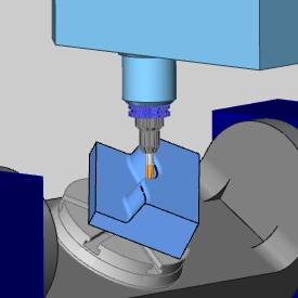
Because of the new tool orientation, the tool holder no longer gouges the part. -
On the Other toolbar, click
Exit Simulation.
Part 10) About Flip Step Over
When using the Tilt Angle at Side of Cutting Direction parameter, it is important to understand the result created when using Flip Step Over.
-
Edit the feature, and click Parameters.
-
In the Surface Paths tab, in the Sorting group, select the Flip Step Over check box.
-
Change the Cutting Method to ZigZag.
-
Click Compute.
Because of the two previous settings, the toolpath now starts at the bottom-left corner of the surface and ends at the top-right corner.
Also, the toolpath now alternates the cutting direction for each slice which eliminates the retract and rapid moves.
-
Simulate the part to view the result.
Simulation shows that the tool orientation is still tilted 45 degrees in the same direction as it was previously, even though the toolpath is now cutting in both directions.
Tip: To cause
the tool side tilt angle to change orientation with each alternating slice,
you must enable Allow Flipping Side Direction. To enable this parameter,
in the Tool Axis Control tab,
next to Side Tilt Definition,
click Advanced. In the Advanced
dialog box, select the ![]() Allow Flipping Side Direction
check box.
Allow Flipping Side Direction
check box.
Part 11) Using Gouge Check
The Gouge Check tab is used next to check the program and correct any further gouges.
-
Edit the feature and navigate to the Gouge Check tab.
-
To turn on a gouge check: in the Status column, above 1, select the
 check box.
In the Check group, select the four check boxes for the Flute, Shaft, Arbor, and Holder. -
In the Strategy and Parameters group, in the first box, select Tilt Tool.
In the next box, select Use Side Tilt Angle. -
To check the values used, click Parameters.
Confirm that the Parameters dialog box shows a Max. Tilt Angle of 90 degrees and a Min. Tilt Angle of -90.
Tip: The Maximum Tilt Angle (range of 0 to 180 degrees) determines the amount of tilting to the left of the cutting direction when using Use Side Tilt Angle. (When using Use Lead/Lag Tilt Angle this determines the amount of tool tilting forward or towards the cutting direction.) The Minimum Tilt Angle (range of -180 to 0 degrees) determines the amount of tilting to the right of the cutting direction. (When using Use Lead/Lag Angle, this determines the amount of tilting backwards from the cutting direction.)
Set the Clearance Angle to 3 degrees.
Click OK.
-
In the Geometry group, the
Drive Surfaces and Check
Surfaces check boxes are selected.
To select the Check
Surfaces, or the surfaces that are gouge checked, click ![]() .
.
Click and drag a window around the entire part to select all surfaces.
Click the Drive Surface to remove it from the selection.
The resulting selection appears as follows.

Click ![]() .
.
To calculate the gouge check, click Compute.
You can compare the results of using the side-tilt angle or creating a gouge check by using only one or the other to calculate the toolpath and then simulating each result.
Tip: When gouge checking a feature, you should always try to get the feature as close as possible to the desired result before you add the gouge check. This way you are only using the gouge check to make small changes to the toolpath. The point here is that you should not rely on the gouge check to fix a poorly created toolpath.
This concludes the tutorial.