How to Create a Multiaxis Parallel to Surface Feature
Introduction
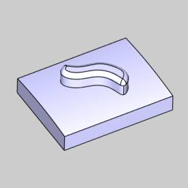
This tutorial explains how to create a Multiaxis feature with the Parallel to Surface toolpath. The toolpath uses a leading surface that is adjacent to the drive surface and creates a toolpath of parallel offsets from the leading surface, on the selected drive surface.
Example File
The BobCAD part file for this tutorial is available for download at: http://bobcad.com/helpfiles. If you are connected to the Internet, you can click the link provided to download and save the Parallel to Surface Example 1 BBCD.zip file. After extracting the zip file, you can open the file to follow along with this example. In the example file provided, the stock and Machine Setup are already defined for the part. The part is simulated using the BC Table-Table machine.
In this example, you learn how to create a toolpath of parallel cuts on a surface using an adjacent surface edge to define the path. A side-tilt angle is applied to show you how to change the default tool orientation. You also learn how to create a margin to offset the tool from the adjacent surface, and how to add a gouge check.
Part 1) Add the Feature
-
In the CAM Tree Manager, right-click
 Machine
Setup and click Mill Multiaxis.
 -
In the Multiaxis Wizard, select Surface and click Parallel to Surface.
-
Click Next>> to go to the Posting settings.
Part 2) Define the Posting Parameters
-
The Work Offset # is automatically set to the value defined in the Machine Setup.
You can change the value here to update the Work Offset # for the feature. -
Click Next>> to go to the Multiaxis Posting settings.
Part 3) Define the Multiaxis Posting Parameters
-
Notice, at the top of the dialog box, that the Use Machine Settings check box is selected.
This means that the Multiaxis Posting parameters for the feature use the same parameters as the machine that is selected in Current Settings.
You can clear the Use Machine Settings check box to define the Multiaxis Posting parameters of the feature separately from the current machine settings.
For this example, no changes are needed. -
Click Next>> to go to the Tool settings.
Part 4) Define the Tool Parameters
-
Under Tool Data, change the Corner Radius to 0.250.
The software automatically searches the Tool Library and loads a tool with the matching parameters, because System Tool is selected. -
To assign a tool holder, click Assign Tool Holder.
In the Milling Tool Holder Library, in the CAT 40 Holder list, click 0.5 inch I.D. Arbor CAT 40.
Click OK. -
Click Next>> to go to the Parameters.
Part 5) Select Geometry
-
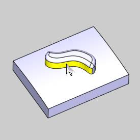
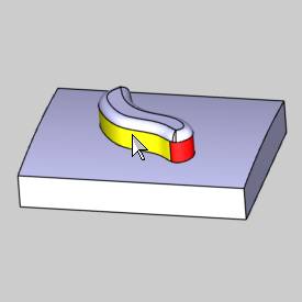
To define the lead surface, in the Surface Paths tab under Pattern, click Single Edge.
-
Select the two surfaces as shown next. (Rotate the part if needed.)
-
To confirm the selections, click
 .
. -
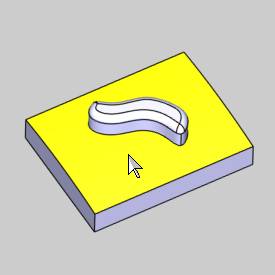
To define where the toolpath is applied, in the Multiaxis Wizard, click Drive Surfaces.
-
Select the top surface as shown next.
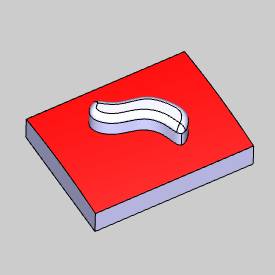
-
To confirm the selections, click
 .
.
The geometry selections are complete.
Part 6) Define the Parameters
-
In the Area group, next to Type, click the down arrow and select Determined by Number of Cuts.
In the Number of Cuts box, type 6.00. -
In the Sorting group, next to Cutting Method, confirm One Way.
-
In the Stepover group, next to Maximum Stepover, type 0.100.
-
At the top of the dialog box, click Link.
Click Retracts.
In the Clearance Area group, confirm that the Type is set to Plane, with the Direction set to Z Axis.
Confirm that the Height is set to 5.000.
This value is automatically set based on the Clearance Plane value from the Machine Setup dialog box. The value from the Machine Setup is only automatically set for the feature when you create the feature. Once the feature is created, you can edit the clearance plane value for the feature in this location (changing the value in the Machine Setup does not update existing Multiaxis features).
Click OK. -
At the bottom of the dialog box, click Compute.
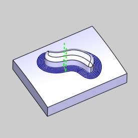
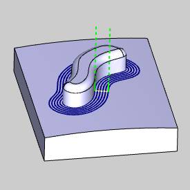
Notice the toolpath at the edge of the island. You can see that this will cut into the island in the middle of the part because the first toolpath pass is at the exact edge where the two surfaces meet.
A margin must be defined.
Part 7) Edit the Feature and Define a Margin
When you computed the toolpath, the ![]() Multiaxis feature
was added to the CAM
Tree.
Multiaxis feature
was added to the CAM
Tree.
-
To edit the feature, right-click
 FeatureMultiaxis, and click Edit.
 -
On the left side of the dialog box, click Parameters.
-
In the Area group, next to Type, click Margins.
-
In the Start Margins box, type the radius of the tool which is 0.250.
(For this example, you could select the Add Internal Tool Radius check box instead of typing the value in the Start Margins box. Either method provides the same result.) -
Click OK.
-
To update the toolpath, click Compute.
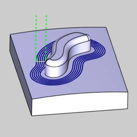
The margin between the surfaces is applied as shown next.
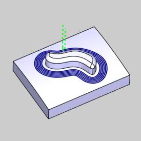
Part 8) Simulation
The next step is to simulate the program to look for any necessary changes.
-
In the quick access toolbar, of the CAM Tree Manager, click

For help with simulation, view Getting Started with Simulation.
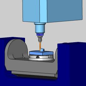
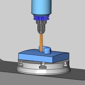
During Simulation, it is shown that the tool axis is always normal to the selected drive surface.
The next step is to add a side tilt angle.
-
When the simulation is finished, click
 Exit
Simulation.
Part 9) Define the Side Tilt Angle
-
Right-click
 Feature Multiaxis, and click Edit.
 -
On the left side of the Multiaxis Wizard, click Parameters.
-
Click Tool Axis Control.
-
Next to Tool Axis Will, confirm that Tilted Relative to Cutting Direction is selected.
-
Next to Tilt Angle at Side of Cutting Direction, type a value of 20.00.
-
Click Compute.
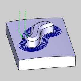
-
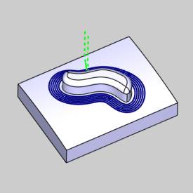
You can see that the side tilt angle has been applied by observing the direction of the plunge (exit and entry) moves (shown in green in the previous image).
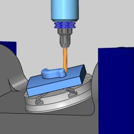
To view the result, simulate the program.
You can see that a 20 degree side tilt angle is added to the tool axis orientation.
Part 10) Create a Gouge Check
For the last step of this tutorial, a gouge check is added to the feature.
-
Edit the feature, and click Parameters.
Click Gouge Check. -
On the left side, in the Status column, select the
 check box above 1.
In the Check column, select the check box for the Flute and the
  Shaft.
In the Strategy and Parameters column, select TiltTool. -
To define the check surfaces, in the Geometry column, with both check boxes selected, click
 .
.
Select all of the island surfaces in the middle of the part, as shown next.
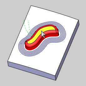
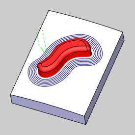
Click ![]() .
.
-
To calculate the gouge check, click Compute.
If any gouges are found, an additional tilt angle is applied to the tool orientation until the feature is no longer gouging.
In this example, no further gouges are found.
This concludes the tutorial.
