How to Create a Multiaxis Wireframe Feature
Introduction
This tutorial explains how to create a Multiaxis feature with the Wireframe toolpath. The wireframe toolpath requires a Drive Curve selection to define the toolpath and Orientation Lines selection along the curve to define the tool orientation.
Example File
The BobCAD part file for this tutorial is available for download at: http://bobcad.com/helpfiles. If you are connected to the Internet, you can click the link provided to download and save the Multiaxis Wireframe Example 1 BBCD.zip file. After extracting the zip file, you can open the file to follow along with this example. In the example file provided, the stock and Machine Setup are already defined for the part. The part is simulated using the BC Table-Table machine.
In this example, you apply a trim cut to the bottom surface of the part. This example explains how to create all the geometry that is needed for the feature directly from the part model. You also learn how the chain direction of the drive curve and orientation lines define the toolpath. An important section here explains how to set the side tilt angle to create the proper tool orientation for the feature. The last part shows how to force the tool past the drive curve in order to cut with a different part of the flute.

Part 1) Create a New Layer
A separate layer is created to hold the geometry that is created in the next part of this tutorial. This makes it easier to hide and show the geometry.
-
Click the
 Layers
tab of the Layer-UCS-Post Manager.
Layers
tab of the Layer-UCS-Post Manager. -
Right-click anywhere in the Layers window, and click Add New Layer.
-
Type Wireframe, and press Enter.
(If for any reason the box lost focus before you renamed the layer, the layer name is shown as New Layer. To rename a layer, right-click the layer name and click Rename.) -
Right-click the Wireframe layer, and select Active Layer, to make this the active layer.
When you create geometry, it is placed on the active layer.
Part 2) Create Geometry for the Feature
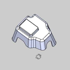
This part of the tutorial explains how to create the wireframe geometry needed to define the feature. The part geometry is used to extract the wireframe geometry.
-
To rotate the part, in the graphics area, click and hold the middle mouse button and drag the mouse.
(If you don't have a middle mouse button, in document toolbar, click Rotate.)
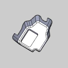
Rotate the part until you can see the bottom side.
-
In the Utilities group, of the Create 2D ribbon, click
 Extract Edges.
 -
In the graphics area, to zoom-in, roll the middle mouse button.
Zoom-in until you can easily view the bottom surface of the part.
(If you don't have middle mouse button, give the graphics area focus, and use + and - on your keyboard to zoom in and out.) -
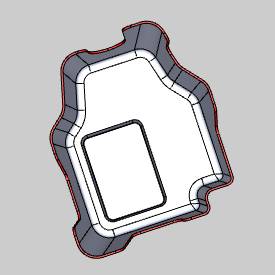
Select the bottom faces of the part as shown next.
Continue to select these surfaces for the entire bottom of the part.
(To pan the view while selecting geometry,
press and hold Ctrl and click
the middle mouse button, then drag in any direction to move the part.
Alternatively, in the document toolbar,
click ![]() Pan.)
Pan.)
Be sure that you select the faces shown and not the edges. Also make sure that you have selected all of the faces around the bottom perimeter of the part.
-
To confirm the selections, click
 . (Alternatively,
you can click OK in the Data Entry Manager.)
. (Alternatively,
you can click OK in the Data Entry Manager.) -
In the Data Entry Manager, click Cancel.
-
In the Layers tab, right-click Part Model, and click Hide.
The extracted edges on the Wireframe layer are now visible.
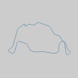
(If for any reason the lines created from extracting the edges are not continuous, repeat the (Extract Edges) steps and select only the surfaces that were missed. Be sure to create the geometry on the Wireframe layer.)
Part 3) Move Orientation Lines to a New Layer
-
Create a new layer and name it Orientation Lines.
-
To enable selection mode, in the document toolbar, click
 .
. -
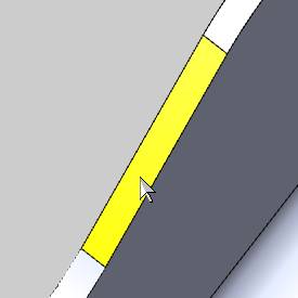
Zoom-in the view to select the lines that connect the inner and outer edge curves. Select all of these connecting lines.
-
After selecting the lines, right-click anywhere in the graphics area, point to ModifyAttributes, and click Color.
In the Color dialog box, select any color that is not the same as the current geometry color.
Now that you have changed the color, it is easier to see if you have missed any orientation lines.
-
In the Quick Selection group, of the Home ribbon, click the down arrow next to
 Pick By Layer, and select
  Pick By Color. (Selection
Mode must still be active.)
Pick By Color. (Selection
Mode must still be active.)
In the Select Color dialog box, click the color of the orientation lines, and click OK.
All of the lines are now selected.
-
Right-click in the graphics area, point to Modify Attributes, and click Layer.
In the SelectLayer dialog box, click Orientation Lines, and click OK. -
In the Layers tab, hide the Orientation Lines layer.
The orientation lines are used later to define the tool orientation.
This process also provides the ability to chain select the remaining curves, one of which is used later for the drive curve selection.
Part 4) Add the Feature
-
In the Data-CAM Tree Manager, click the CAM Tree tab.
-
Right-click
 Machine
Setup and click Mill Multiaxis.
Machine
Setup and click Mill Multiaxis. -
In the Multiaxis Wizard, confirm Wireframe is selected.
-
Click Next>> to go to the Posting settings.
Part 5) Define the Posting Parameters
-
The Work Offset # is automatically set to the value defined in the Machine Setup.
You can change the value here to update the Work Offset # for the feature.
-
Click Next>> to go to the Multiaxis Posting settings.
Part 6) Define the Multiaxis Posting Parameters
-
Notice, at the top of the dialog box, that the Use Machine Settings check box is selected.
This means that the Multiaxis Posting parameters for the feature use the same parameters as the machine that is selected in Current Settings.
You can clear the Use Machine Settings check box to define the Multiaxis Posting parameters of the feature separately from the current machine settings.
An example usage is explained later.
-
Click Next>> to go to the Tool settings.
Part 7) Define the Tool Parameters
-
In the Tool Data group, set the Diameter to 0.375 and the Corner Radius to 0.00.
-
Notice that the tool data is updated using a tool from the Tool Library (using System Tool).
-
Click Next>> to go to the Parameters.
Part 8) Select Geometry
-
On the Surface Paths tab, in the Edit Curves group, click Drive Curves.
(The Orientation Lines layer must remain hidden.) -
In the graphics area, hold down Shift and select the inner-surface edge that you extracted to the Wireframe layer.
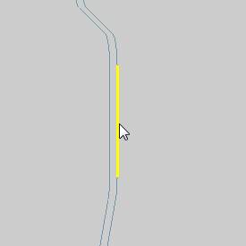
-
To confirm the selection, click
. -
In the Edit Curves group, click Orientation Lines.
Right-click anywhere in the Layers Manager, and click Hide All.
Right-click the Orientation Lines layer, and click Show.
(You may need to zoom-in to see the lines, remember that they are very short in length.)
In the Selection group, of the Home ribbon, click ![]() Select All.
Select All.
This selects all of the currently visible geometry.
-
To confirm the selection, click
.
Part 9) Set the Direction of the Orientation Lines
You must confirm that all of the Orientation Lines share the same chain direction. For this example, the chain direction of all Orientation Lines must point towards the outside of the part. If they do not share the same direction, an error message displays when you compute the toolpath.
-
To view the chain direction, first click Finish to close the wizard.
Tip: In this part of the tutorial, you must set the chain direction for the Orientation lines. To make it easier to set the direction, show the Part Model layer and rotate the view in the graphics area so that the bottom of the part is showing (or press Ctrl+4). When you zoom in and out to check the chain direction, this makes it easier to see if each line is pointing in the appropriate direction. Hide the Part Model layer again after completing this part.
Make sure that the Orientation Lines and Part Model layers are visible.
-
In the CAM Tree, right-click Orientation Lines, and click Modify Start Point.
(You may need to expand the Geometry folder under the
 Multiaxis
operation.)
Multiaxis
operation.) -
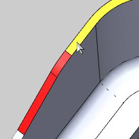
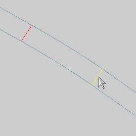
The chain direction of each orientation line is now visible.
Because the orientation lines are open chains, a start point and an end point indicate the chain direction. -
To change the chain direction, click the entity near the end to which the chain direction should point.
This task is most easily accomplished by first zooming-in until the chain direction is easy to view. After zooming in, use panning to follow along the bottom of the part as you set the chain direction of each line.
Tip: When setting the chain direction (using Modify Start Point), you do not have to click the entity directly. You can also click in the graphics area in the direction that you want the chain direction to point. When using this method, click in close proximity to the entity you are modifying. Use whatever method you find to work the best for you.
-
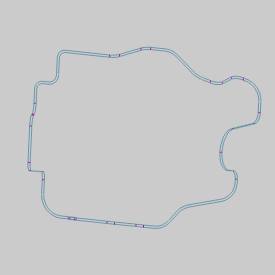
Continue this process until the direction of all orientation lines points to the outside of the part.
To confirm the selections, click ![]() .
.
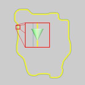
Important: As
shown in this example, the chain direction of the Orientation Lines is
set to start at the tool tip and point back towards the spindle. The chain
direction does not point towards
the tool tip.
When
computing the toolpath, if a message displays about antiparallel lines,
then the Orientation Lines are not all pointing in the same direction.
Repeat Modify Start Point and correct the backwards chain direction.
Part 10) Set the Direction of the Drive Curve
-
Before moving on, the chain direction of the drive curve must also be set.
For this example, our reference for the direction (clockwise or counterclockwise) is the top view.
Press Ctrl+1 to select the top view of the part. (The Part Model layer must be hidden and the Wireframe layer must be visible.)
In the CAM Tree, right-click Drive Curves, and click Modify Start Point.
-
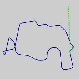
Zoom-in to view the start point and note the direction.
-
Regardless of the current chain direction, click
to exit Modify Start Point. -
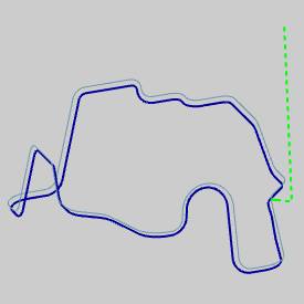
If the chain direction was clockwise, right-click Drive Curves, and click Reverse Direction.
If the chain direction was already counterclockwise, no change is needed.
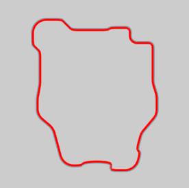
From the top view, the chain direction appears as follows.
Part 11) Define the Parameters
-
To edit the feature, right-click
 FeatureMultiaxis, and click Edit.
Click Parameters on the left side of the dialog box.
In the Pattern group, the Maximum Snap Distance defines what Orientation Lines are included in the toolpath calculation. This distance is measured from the selected Drive Curve.
For this example, because the orientation lines touch the drive curve, the default value of 0.100 is used.
-
For this example, because the drive curve chain direction is counterclockwise, set the Machining Side to Right.
-
In the Sorting group, next to Direction for One Way Machining, select Follow Curve Chaining.
-
To create the toolpath, click Compute.
-
The program is not yet ready to simulate as the tool is currently cutting with the tip of the tool pointing to the surface edge from underneath the part. (With the current tool orientation, the feature could not be run on the machine as set up for this example.)
This is not the same orientation as the selected (orientation line) geometry.

Important: In order to have the tool orientation follow same orientation of the selected Orientation Lines, you must set the Tilt Away from Line angle value to 0.000 degrees.
Part 12) Define the Side-Tilt Angle
-
Edit the feature, and click Parameters.
-
Click the Tool Axis Control tab.
Notice the tilting strategy, next to Tool Axis Will, is set to Tilted Relative to Cutting Direction. -
In the Tilt Away from Line box, type 0.000.
-
Click Compute.
The toolpath is now offset to the bottom side of the part.
The tool orientation is now properly aligned with the selected orientation lines.

-
Be sure to show the Part Model layer before simulating, or no workpiece geometry is passed to simulation.
-
To view the program, in the quick access toolbar, of the CAM Tree Manager, click
 .
.
During simulation, the tool orientation is now the same as the orientation lines.

-
To close simulation, click
 Exit Simulation.
For more help using simulation, view Getting Started with Simulation.
Adjust the Machine Table Rotation
When you simulate the program, the machine table is sometimes rotated in a way that doesn't allow you to view the part without rotating the view of the machine. You can change the Angle Pair settings for the feature to modify the table rotation used in simulation and in the posted code.
-
To edit the feature, in the CAM Tree, right click
FeatureMultiaxis,
and click Edit. -
Click the Multiaxis Posting icon in the tree.
-
Clear the Use Machine Settings check box.
-
In the Angle Pair group, next to Use, select Other Solution.
When you simulate the program again, you can now view the part being cut from the opposite side of the machine.
The table is rotated to use the other solution to the rotation angles of the primary and secondary rotary axes (angle pair). This changes the posted output of the program as well as the simulation.
Tip: You don't have to compute the toolpath to update this setting for simulation, but you must Post the program to update the code if has already been posted.
Part 13) Axial Shift
If you want to force the tool past the drive curve in order to cut using more of the flute, or a different part of the flute, you can use the Axial Shift parameters.
-
Edit the feature, click Parameters, and click the Utility tab.
-
In the Axial Shift group, notice the option Constant for Each Contour.
This shifts the tool by the specified amount for the entire toolpath. -
In the To box, type -0.250.
(Negative values cause the tool to in-feed, and positive values retract the tool.) -
To add the changes, click Compute.
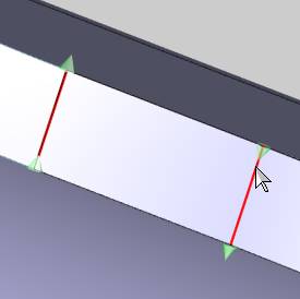
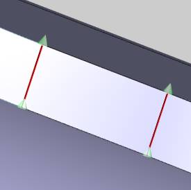
The result is visible in the toolpath display. (The toolpath moves towards the inside of the part.)
The following images show the tool position before and after adding the Axial Shift.


This concludes the tutorial.