How to Create a Multiaxis Morph Between 2 Curves Feature
Introduction
This tutorial explains how to create a Multiaxis feature with the Morph Between 2 Curves toolpath. The feature requires the selection of two separate geometry curves and the drive surfaces to which the toolpath is applied. The feature creates offsets of each curve and blends the two offsets together (morphs) to create the toolpath on the selected drive surfaces.
Example File
The BobCAD part file for this tutorial is available for download at: http://bobcad.com/helpfiles. If you are connected to the Internet, you can click the link provided to download and save the Morph Between 2 Curves Example 1 BBCD.zip file. After extracting the zip file, you can open the file to follow along with this example. In the example file provided, the stock and Machine Setup are already defined for the part. The part is simulated using the BC Table-Table machine.
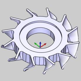
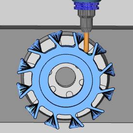
In this example, a finishing type toolpath strategy is applied to the floor surface that lies between the blades of a blisk (bladed disk). It is shown how the surface normal direction defines the tool orientation and how a tilting strategy is applied to change this default tool orientation. To learn more about controlling the toolpath created in this example, view the Morph Between 2 Surfaces example which uses the same part model.
Part 1) Add the Feature
-
In the CAM Tree Manager, right-click
 Machine
Setup and click Mill Multiaxis.
Machine
Setup and click Mill Multiaxis. -
In the Multiaxis Wizard, click Surface and click Morph Between 2 Curves.
-
Click Next>> to go to the Posting settings.
Part 2) Define the Posting Parameters
-
The Work Offset # is automatically set to the value defined in the Machine Setup.
You can change the value here to update the Work Offset # for the feature. -
Click Next>> to go to the Multiaxis Posting settings.
Part 3) Define the Multiaxis Posting Parameters
-
Notice, at the top of the dialog, that the Use Machine Settings check box is selected.
This means that the Multiaxis Posting parameters for the feature use the same parameters as the machine that is selected in Current Settings.
You can clear the Use Machine Settings check box to define the Multiaxis Posting parameters of the feature separately from the current machine settings.
For this example, no changes are needed (more information is provided later). -
Click Next>> to go to the Tool settings.
Part 4) Define the Tool Parameters
-
In the Tool Data group, clear the
 System Tool check box.
 -
Set the Diameter to 0.500, the Flute Length to 2.500, and the Corner Radius to 0.250.
-
Click Next>> to go to the Parameters.
Part 5) Select Geometry
For the geometry selections in this example, the original part model is hidden from view, and a separate layer is shown that contains only the surfaces that are necessary for this example. The position of these surfaces in the workspace is exactly the same as they are on the model.
-
To define the first curve, in the Surface Paths tab under Pattern, click First.
-
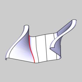
Select the first edge curve as shown next.
(In the Layers Manager, the Part Model layer is hidden and the Surfaces layer is visible. The Surfaces layer is used for the geometry selections.)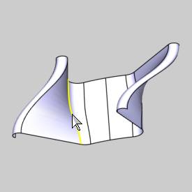
-
To confirm the selection, click
 .
. -
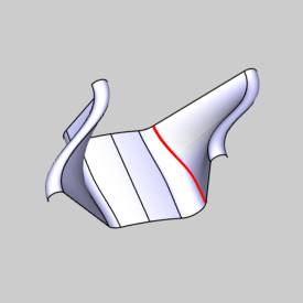
To define the second curve, under Pattern, click Second.
Select the second curve as shown next.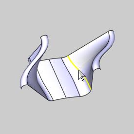
-
To confirm the selection, click
. -
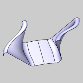
To define the surfaces to machine, click Drive Surfaces.
Click to select the four bottom surfaces as shown next.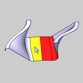
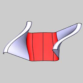
-
To confirm the selection, click
.
The next step is to define the parameters for the feature.
Part 6) Define the Parameters
-
In the Area group, next to Type, select Full, Start and End at Exact Surface Edges.
-
In the Sorting group, next to Cutting Method, select Zigzag.
-
At the top of the dialog, click Link.
In the Links Between Slice group, next to Small Moves, click the down arrow and select Blend Spline.
In the Small Move Size box, change the value to 500. -
Click Retracts.
Next to Type, select Cylinder, and set the Direction to Z Axis.
In the Radius box, type 6.00.
Click OK. -
At the bottom of the Multiaxis Wizard, click Compute.
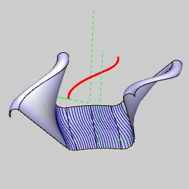
The result is shown next.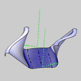
-
If you were to simulate the program now, you would see that the current tool axis orientation follows the surface normal direction of the selected surfaces. This is because the default tilting strategy, Tilted Relative to Cutting Direction, uses the surface normal direction. (To simulate the part now shows many gouges as the tool follows the surface normal direction, but it also shows the tool orientation that is created from the surface normal.)
In the document toolbar, click Surface Normal.
(You can also use the shortcut key, N.)
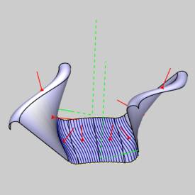
In the center of the drive surfaces, the tool axis following the surface normal is not a problem. It is when the tool cuts near the outer edge curves that the tool axis orientation gouges the part. The tool orientation at the outer edge curve is shown in the next image.
The next step is to add a tilt curve to define the tool axis orientation.
Part 7) Edit the Feature and Define the Tool Axis Control
When you computed the toolpath for the feature, the ![]() Multiaxis feature was added to the
CAM Tree.
Multiaxis feature was added to the
CAM Tree.
-
To edit the feature, right-click
 Feature Multiaxis, and click Edit.
 -
On the left side of the Multiaxis Wizard, click Parameters.
At the top of the dialog, click Tool Axis Control. -
Next to Tool Axis Will, select the tilting strategy, Tilted Through Curve.
Next to Curve Tilt Type, select From Start to End for Each Contour. -
To define the tilt curve, click Tilt Curve.
In the Layer Manager, right-click the layer Tilt Curve, and click Show Layer. -
Click to select the spline curve as shown next.
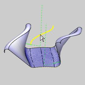
-
To confirm the selection, click
. -
To add the changes, click Compute.
The result is shown next.
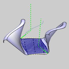
Notice that the toolpath has moved away from the selected edge curves. The toolpath shows the tool tip position, which is no longer at the exact edge curve. This is the result of the new tool tilting that was created with the selected tilt curve.
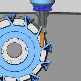
Part 8) Simulate the Program
- In the quick access toolbar, of the CAM Tree Manager, click
 .
.
To learn more about using simulation, view Getting Started with Simulation.
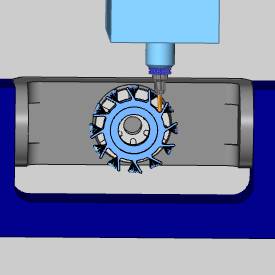
When you simulate the program, you can see that the tool axis is now always tilted through the selected Tilt Curve.
-
To close simulation, click
 Exit Simulation.
Adjust the Machine Table Rotation
When you simulate the program, the machine table is sometimes rotated in a way that doesn't allow you to view the part without rotating the view of the machine. You can change the Angle Pair settings for the feature to modify the table rotation used in simulation and in the posted code.
- To edit the feature, in the CAM
Tree, right click FeatureMultiaxis,
and click Edit.
- Click the
Multiaxis Posting icon in the tree.
- Clear the Use
Machine Settings check box.
- In the Angle
Pair group, next to Use,
select Other Solution.
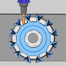
When you simulate the program again, you can now view the part being cut from the opposite side of the machine.
The table is rotated to use the other solution to the rotation angles of the primary and secondary rotary axes (angle pair). This changes the posted output of the program as well as the simulation.
Tip: You don't have to compute the toolpath to update this setting for simulation, but you must Post the program to update the code if has already been posted.
This concludes the tutorial.