Ruled Surface Radius Limit
Introduction
This topic will explain the Ruled surface radius limit option, describe where to find it, and provide an example.
Ruled surface radius limit
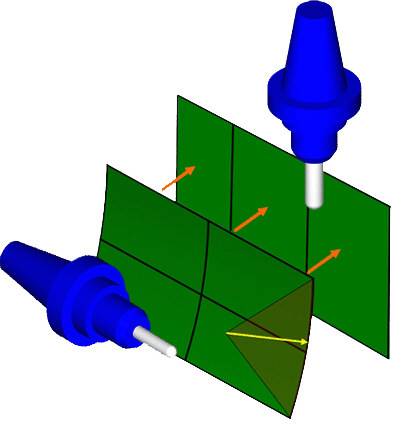
Swarf machining is defined by having a contact line between the cutter and the surface. Such line contact can be achieved only if the surfaces are ruled. Surfaces are spanned in the U- and V-domain and a ruled surface must have an unlimited radius in one of these directions. In most practical cases the surfaces look ruled but after analysis of the surfaces, the results show they do not have an unlimited radius in one direction. Instead, they have a large radius in one direction which can be considered almost flat. This limit radius is defined by the Ruled Surface Radius Limit parameter. When swarf machining with untrue ruled surfaces you must analyze the surface radius in the swarf direction and provide a radius limit accordingly to allow the system to use the surfaces as drive surfaces.
Note:
• The Ruled Surface Radius Limit is only
available with tool axis option Tilted Relative to Cutting Direction
combined with the side tilt definition Follow Surface Isometric Directions.
• Setting this radius small or large does not affect
the resulting toolpaths in terms of gouging. Gouge check must always
be done for swarfing by tilting the tool using the side tilt angle.
In other words, non-ruled (free form) surfaces can be swarf machined
without any gouges using this parameter in an appropriate way combined
later with gouge checking.
Navigation
To access Ruled surface radius limit :
- The Ruled surface radius limit option can be found on the Tool axis control page.
Click to view the options in the drop down next to Tool axis will... and select Be tilted relative to cutting direction. - With that option selected, the Side tilt definition options will become visible further down the page.
- Click to view the drop down list and select Follow surface iso direction.
- With that option select, click the Advanced button below.
The Advanced option for tilting relative to cutting direction dialog appears, with the Ruled surface radius limit option in the second group.
Example
-
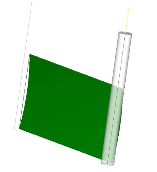
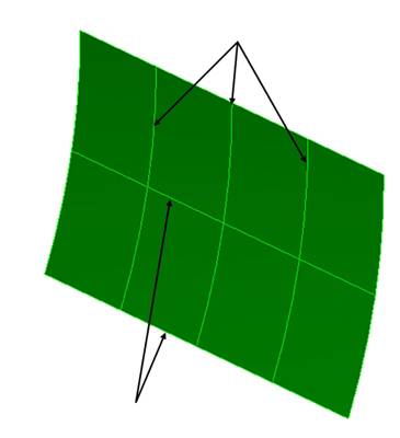
In this example there is a curved surface with a radius of 147.727 mm (this example is distended because usually the radii are smaller, but it is a good example to show how the function works). The toolpath is a single segment parallel to the lower edge with a tool axis tilted 90 degrees to the side. In the vertical direction the isometric lines of the surface are not ruled, instead, the horizontal isometric direction is ruled.
|
Curved Vertical Isometric Direction |
|
|
Ruled Horizontal Isometric Direction |
-
So the system assumes the horizontal isometric direction to which to orient the tool axis, although the side tilt angle is 90 degrees. The toolpath is wrong. The radius limit is set to 148 mm. That means that all surfaces with the radius bigger than 148 mm are assumed as ruled. Our surface with the radius 147.727 mm is smaller than this value, so not ruled.
-
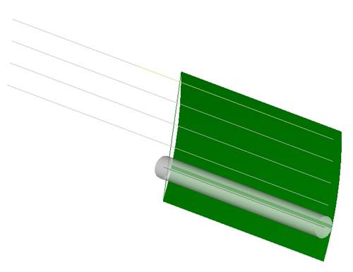
Now the Ruled Surface Radius Limit is set to 147 mm to correct the toolpath.