Entity Modification
Introduction
This topic will explain Entity Modification, provide quick steps on how to use it, and provide links to related topics.
Entity Modification
There are numerous ways to modify geometry in the graphics area. This help topic explains the items that are available in the Edit menu (not the Utility functions). Most of these functions are not available until an entity is selected in the graphics area.
Navigation
To access the Entity Modification functions, after selecting geometry, do one of the following:
-
Right-click in the graphics area, click Modify To Current, Modify Entities, or Entity Modify.
-
In the Modify group, of the Home ribbon, click the icon of the desired function.
The Entity Modify Functions
Modify Entity Attributes
For the following functions, you must first select an entity, and then select one of the following.
- Color - opens the Modify Color dialog box. Click the new color, and the selected entity is updated.
- Layer - opens the Select Layer dialog box. Click the layer to which the selected entity is moved, and click OK.
- Line Style - opens the Line Style dialog box. Click the new line style to apply to the selected entity, and click OK.
- Point Style - opens the Point Style dialog box. Click the new point style to apply to the selected entity, and click OK.
Modify Entity To Current
The following functions are used with the current software settings, such as the current color and line style that are displayed (and can be changed) in the Status Bar at the bottom-right side of the user interface. The current settings must be different than that of the selected entity to use these functions.
-
 Modify to CurrentColor
- changes the selected entities to the active color.
Modify to CurrentColor
- changes the selected entities to the active color. -
 Modify to Current Line Style - changes the selected
entities to the active line style.
Modify to Current Line Style - changes the selected
entities to the active line style. -
 Modify to CurrentLayer
- places the currently selected entities on the active layer.
Modify to CurrentLayer
- places the currently selected entities on the active layer. -
 Modify
to Current Point Style - changes the selected points to the
current point style.
Modify
to Current Point Style - changes the selected points to the
current point style.
Change Line Style
-
 Change Style to Solid - converts selected entities
to a solid line style.
Change Style to Solid - converts selected entities
to a solid line style. -
 Change Style to Dashed - converts selected entities
to a dashed line style.
Change Style to Dashed - converts selected entities
to a dashed line style.
Entity Modify
-
 Entity Modify - opens the
Data Entry Manager so you can modify the parameters of the selected
entity. You must select a single entity (whether or not it is a part
of a contiguous entity chain), such as one line or one arc, or this
function is unavailable. This option is used for wireframe entities,
including text. To learn more, view How
to Modify Wireframe Entities.
Entity Modify - opens the
Data Entry Manager so you can modify the parameters of the selected
entity. You must select a single entity (whether or not it is a part
of a contiguous entity chain), such as one line or one arc, or this
function is unavailable. This option is used for wireframe entities,
including text. To learn more, view How
to Modify Wireframe Entities.
Other Modification Tools
To learn how to move, rotate, and trim geometry, as well as the many other ways that geometry can be altered, view the Utility Functions. Dynamic changes can be made with the utilization of The CAD Tree.
Example
Part 1) Modify an Arc
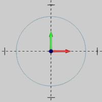
The following image shows an arc with a 0.750 inch radius that we want to change to a 0.500 inch radius.
To modify this entity, we use the following steps.
-
In the document toolbar, click
 Select Mode.
 -
Point to the arc in the graphics area, so that it displays in the system highlight color, and click to select it.

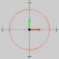
The arc changes to the selection color. Notice that when we point to the entity, the entire arc displays in the highlight color. This shows us that this is a single entity and can be modified. -
Right-click anywhere in the graphics area, and click Entity Modify.
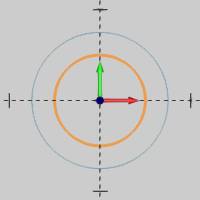
The Arc parameters display in the Data Entry Manager, and the preview appears.
You can change any of the available parameters as needed. For this example, we only change the radius. -
Change the Radius value to 0.500, and press Tab to update the CAD preview.
-
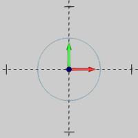
To finish modifying the entity, click OK.
This same process can be applied to modify point, line, or text entities.
Note: If you have created text with the Vectorize option turned off, you can modify the parameters for that text entity, including the letters. If the vectorize option was turned on when creating the text, then only the individual line and arc entities of the text can be modified.
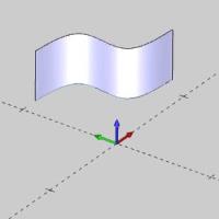
Part 2) Modify a Spline
When you modify a spline, the process is slightly different than other entity types. Modifying a spline allows you to change the spline control points.
The following image show a surface that was extruded from a spline curve.
To modify the spline that created the surface, we use the following steps.
-
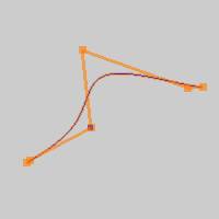
In the CAD Tree, we right-click our Extrude Curve feature, and click Suppress/Unsupress.
This suppresses the extrude curve feature so that only the wireframe displays. Note that this step isn't necessarily required. If the spline is created on one CAD layer and the surface is on another CAD layer, we can just hide the surface layer. Also, the blank function can be used to hide the surface temporarily. Either way, we just need to make the spline visible so we can select it.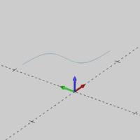
-
On the document toolbar, click the
 Select Mode icon.
Click to select the spline in the graphics area.
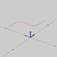
Notice again, that the entire spline highlights when we point to it. This is how we know it is a single entity, and thus can be modified. -
In the Modify group, of the Home ribbon, click
Entity Modify.
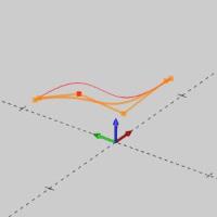
The Modify Curve dialog displays in the Data Entry Manager, and the CAD preview displays in the graphics area.
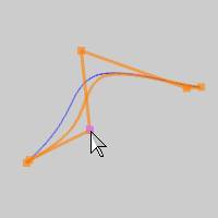
Notice the control points that display. You click these points to enable modification and then click to place them, or change their values in the Coordinate group of the Data Entry Manager. -
Next, click to select one of the control points so you can modify it.

-
Click anywhere to place the control point.

Note that you can also select a point or the snap point of another wireframe entity when modifying a spline control point.
-
In the Data Entry Manager, click OK to finish modifying the spline.

-
Now because we modified a wireframe entity that is the input to a surface feature (extrude curve), we need to update the Extrude Curve Feature.
Right-click the Extrude Curve feature in the CAD Tree, and select Suppress/Unsppress.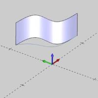
The surface reappears. - Right-click the Extrude Curve feature in the CAD Tree, and select Rebuild.
The surface is automatically rebuilt using the modified spline geometry.

Note: As long as we are changing the geometry that is already associated with a feature in the CAD Tree, we can simply rebuild. If we created new geometry, or needed to assign different geometry to it, we would need to right-click the geometry of the feature in the CAD Tree, choose Re/Select, then associate the new geometry before rebuilding.
This concludes the example.