The Chuck Configuration Dialog
Introduction
The Chuck Wizard is used to define a chuck for multiaxis mill turn machines. This dialog box is accessed from the Machine Definition of the Current Settings.
Navigation
To access the Chuck Configuration dialog from the Machine Definition, do one of the following:
- Right-click a Chuck item in the machine tree, and click Edit.
- After selecting a Chuck item in the machine tree, click the Chuck Wizard button.
The Chuck Wizard displays.
Parameters
Rotation Axis
The rotation axis of the chuck is set in reference to the machine zero coordinate system. (This defines the rotation axis of the chuck)
-
X - is selected when the rotation axis of the chuck is parallel to the X-axis of the machine.
-
Y - is selected when the rotation axis of the chuck is parallel to the Y-axis of the machine.
-
Z - is selected when the rotation axis of the chuck is parallel to the Z-axis of the machine.
-
User Defined - is selected when the rotation axis of the chuck is not parallel to the X, Y, or Z axes. Use this option to define a custom chuck rotation axis with the Direction and Base Point parameters.
Direction
The Direction group displays the direction vector of the selected Rotation Axis. When selecting X, Y, or Z, this in an informational display only. (For example, when set to Y, the vector displays as X0 Y1 Z0.) When selecting User Defined, you can type the XYZ values to determine the custom direction vector.
Base Point
This parameter determines the distance from the machine zero location or the front face of the chuck, to the chuck rotation axis. (The face of the chuck is aligned to machine zero location when creating the geometry files).
-
X - is the distance from the machine zero to the chuck rotation axis along the X-axis.
-
Y - is the distance from the machine zero to the chuck rotation axis along the Y-axis.
-
Z - is the distance from the machine zero to the chuck rotation axis along the Z-axis.
Index Direction
This parameter defines the direction for positive rotation of the chuck. (Note that changing from CCW to CW automatically adjusts the Rotation Axis Direction (XYZ) vectors to negative.)
![]() CW
(clockwise) - sets the positive rotation direction to a clockwise rotation.
CW
(clockwise) - sets the positive rotation direction to a clockwise rotation.
![]() CCW (counterclockwise) - sets the positive rotation direction to a counter clockwise rotation.
CCW (counterclockwise) - sets the positive rotation direction to a counter clockwise rotation.
Chuck Body
![]() Parameters - allows the dimensions of the chuck body the be defined with user entered values for each of the parameters:
Parameters - allows the dimensions of the chuck body the be defined with user entered values for each of the parameters:
.
-
Body Diameter - sets the overall diameter of the chuck.
-
Inner Diameter - sets the inner diameter of the chuck.
-
Body Thickness - sets the thickness of the chuck.
Flip Orientation - The direction of the extruded chuck is determined by the rotation axis. The default direction of the extrusion is along the positive of the rotation axis vector. This can be changed by selecting the following check box. ![]() - With this check box cleared, the chuck body is extruded along the positive direction of the rotation axis.
- With this check box cleared, the chuck body is extruded along the positive direction of the rotation axis. 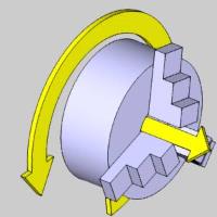
![]() - With this check box selected, the orientation reverses and is extruded along the negative direction of the rotation axis vector.
- With this check box selected, the orientation reverses and is extruded along the negative direction of the rotation axis vector. 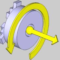
![]() STL - allows the dimensions of the chuck body the be defined with the selection of an STL model:
STL - allows the dimensions of the chuck body the be defined with the selection of an STL model:
- Load STL ... - click to select an STL.
STL File Unit - allows you to specify the units used in the creation of the STL model.
-
 Inch - sets the model units to inch.
 -
 Metric - sets the model units to metric.
Jaws
Jaw Definition
- Number of Jaws - this determines how many jaws are on the chuck. The jaws are all equally spaced around the chuck.
Limits
- Min - defines the minimum amount of travel toward the center of the chuck.
- Max - defines the maximum amount of travel toward the outside of the chuck.
- Initial - defines the initial position of the jaws.
First Jaw Angle
- Angle - defines the initial vector direction of the first jaw. Subsequent jaw vector directions are calculated from this position.
Geometry
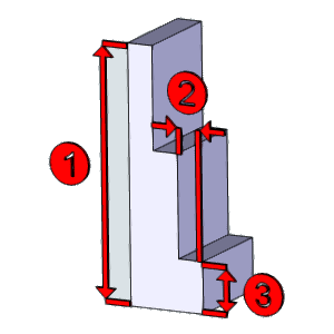
![]() Parameters - allows the dimensions of the chuck body the be defined with user entered values for each of the parameters:
Parameters - allows the dimensions of the chuck body the be defined with user entered values for each of the parameters:
.
-
Jaw Height (1) - sets the height of the jaw.
-
Step Height (2) - sets the height of steps in the jaw.
-
Step Depth (3) - sets the depth of steps in the jaw.
- Thickness - sets the thickness of the jaw.
![]() STL - allows the dimensions of the chuck body the be defined with the selection of an STL model:
STL - allows the dimensions of the chuck body the be defined with the selection of an STL model:
- Load STL ... - click to select an STL.
- Jaw Height (1) - sets the height of the jaw so the middle point can be used to flip the jaw when necessary.
STL File Unit - allows you to specify the units used in the creation of the STL model.
-
Inch - sets the model units to inch.
-
Metric - sets the model units to metric.
OK - accepts the changes and exits the Chuck Configuration dialog.
Cancel - discards the changes and exits the Chuck Configuration dialog.