The Turret Configuration
Introduction
This topic explains how to define a turret for a mill-turn machine in
Bob
The Turret Configuration
The Turret Configuration is accessed from the machine definition of the Current Setting Default dialog box when a mill-turn machine is selected. View the Current Settings Default topic from the previous link to learn how to add a turret to the machine definition.
Navigation
To access the Turret Configuration from the Machine Definition, do one of the following:
- Right-click a Turret item in the machine tree, and click Edit.
- After selecting a Turret item in the machine tree, click the Turret Wizard button.
The Turret Configuration displays, which contains two pages: Parameters and Mounting Locations.
Parameters
In the Parameters page, you define the turret dimensions, number of stations, rotation axis, and you can also load an .stl file for the turret that is used in full machine simulation. (If you don't load an .stl file, the software creates a basic polygon shape based on the settings you define.) The values that you enter are based on the turret with no tools or adapters mounted.
It is important to properly define all values on the Parameters page before modifying settings on the Mounting Locations page, as the turret parameters are used to define the Mounting Location parameters.
Define the Turret Parameters
Number of Stations
This value defines how many stations, or locations at which a tool or adapter can be mounted, exist on the turret. Note that a single station may have up to three mounting locations: front, side, or back, or it may only have a single mounting location, for example, the side.


Turret Diameter/Flat to Flat Distance
This parameters defines the diameter of the turret, which can be measured as the flat-to-flat distance between opposing turret stations (for non-round turrets).

Turret Thickness
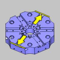
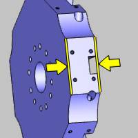
This value is the thickness or width at the side of the turret, or the distance between the front and back faces of the turret. Note that the value is the width of the mounting location, which may or may not be the same as the total thickness of the turret (as shown in the following images). Also note that you can enter a negative value for the thickness, for example, for a lower turret where this distance is in the negative axis direction.

Define the Turret Rotation Parameters
Rotation Axis
The rotation axis must be set based on the orientation of the turret in reference to the machine zero coordinate system.
-
X - is selected when the rotation axis of the turret is parallel to the X-axis of the machine.

-
Y - is selected when the rotation axis of the turret is parallel to the Y-axis of the machine.

-
Z - is selected when the rotation axis of the turret is parallel to the Z-axis of the machine.

-
User Defined - is selected when the rotation axis of the turret is not parallel to the X, Y, or Z axes. Use this option to define a custom turret rotation axis with the Direction and Base Point parameters.
Direction
The Direction group displays the direction vector of the selected Rotation Axis. When selecting X, Y, or Z, this in an informational display only. (For example, when set to Y, the vector displays as X0 Y1 Z0.) When selecting User Defined, you can type the XYZ values to determine the custom direction vector.
Base Point
This parameter determines the distance from the machine zero location (which is the front face of the lathe spindle) to the turret's rotation axis.
-
X - is the distance from the machine zero to the turret's rotation axis along the X-axis.
-
Y - is the distance from the machine zero to the turret's rotation axis along the Y-axis.
-
Z - is the distance from the machine zero to the turret's rotation axis along the Z-axis.
The following image provides an example of how the base point distance is measured for the most common turret Rotation Axis, the Z-axis. The image shows the coordinate system (machine zero) at the face of the main (lathe) spindle, and the turret as aligned for defining the machine. For the example turret, the Base Point X value is updated to the distance shown. (Note that this is a positive value because it is in the positive X direction.)

Index Direction
This parameter defines the direction in which the turret rotates in order to index to the next (consecutive) numbered turret station. This can be set to either CW, clockwise, or CCW, counterclockwise. (Note that changing from CCW to CW automatically adjusts the Rotation Axis Direction (XYZ) vectors to negative.)

Define the Turret Geometry for Full Machine Simulation
Load STL
This button displays the Open dialog box for you to locate and select a .stl file that represents the actual turret. Be sure to select the appropriate STL File Unit of Inch or Metric first, based on the unit type in which the model was created. The model is used in machine simulation, so make the model as basic or as detailed as you want to see in machine simulation. Note that if you do not select an .stl file for the turret, the software creates one for machine simulation based on the parameters you define for the turret. (A basic polygon is created.)
Important: Be sure to orient the .stl file with it aligned to the machine zero, or the coordinate system used to align the machine geometry files, the same way that it is on the physical machine. This is shown in the following images for an upper and lower turret, respectively. Note that each turret is saved to a separate .stl file.
Upper Turret Alignment


Lower Turret Alignment


Machine with Turrets at Zero

Mounting Locations
In this page, you define the mounting locations that are used when mounting tools or adapters at each turret station. In other words, you are defining the orientation of the coordinate system at each mounting location. The Mounting Locations page contains a preview window of the defined turret and all mounting locations to help guide you through creating the proper settings. There is some flexibility in how you define the mounting location coordinate systems, but generally these are aligned to follow the same general axes directions as the machine.
Mounting Locations Table and Preview
The table that displays on the Mounting Locations page contains all of the parameters that define the coordinate systems used for each mounting location on the turret. The preview window updates to show the changes that you make and displays either the .stl geometry file, if you assigned one, or a basic polygon to show the current turret definition.
Selecting Mounting Locations
When you click a mounting location in the table, the coordinate system highlights in the preview window. This is used in conjunction with the mounting location display options. To select more than one mounting location in the list, use the following controls.
- Click anywhere in the row of a mounting location to select it.
- Hold down the Ctrl key and click another mounting location to add it to or remove it from the selection.
- After selecting one mounting location, hold the Shift key and click another to select all mounting locations in between the first and second selections.
Mounting Location Display Options
Options are provided to determine which mounting location coordinate systems display in the preview window. You can select to Display All, None, or only the mounting locations that are currently selected in the mounting locations table (Display Selected). It can be helpful to use the Display Selected option while modifying the parameters to make it easier to view the changes.
View Controls
The turret preview window uses the standard mouse controls for altering the viewing position of the preview.
- You can Rotate the view by dragging with the left mouse button in the preview window. (You can also drag with the middle mouse button.)
-
You can Pan the view by holding down Ctrl (on the keyboard) and dragging with the middle mouse button.
-
You can Zoom in or out using the scroll wheel (rolling the middle mouse button forward or backward).
-
Press F to activate the Fit All command and fit the turret preview to the window
-
Press T to toggle the transparent view of the turret
Editing Mounting Locations
To edit a value in the mounting locations table, click the value directly to make it available for editing. Type the new value and either press Enter to finish, or press Tab to move to the next parameter. The following parameters can be edited in the table.
Use Default Mounting Locations
Click this button to calculate all of the mounting location parameters in the table using the current values from the Parameters page. Note that this resets all values in the table.
Radial Distance
This value is the distance (radius) from the center of the turret to the mounting location coordinate system.

Angle
This value is the degrees of rotation needed to index to the mounting location in reference to the zero degree location (cutting position).

Axial Distance
This value is the distance along the rotation axis (X, Y, or Z) of the turret, from zero to the mounting location coordinate system.

Delete
The delete button removes the mounting locations that are currently selected in the mounting locations table. You can remove the mounting locations that the turret does not contain. For example, some turrets only mount tools to the side face, so all front face and back face mounting locations can be deleted in this situation. (This removes unnecessary mounting locations from the tool crib so only the appropriate locations display.)
Mounting Orientation
The Mounting Orientation options determine the orientation of the coordinate systems (axes directions) for all mounting locations. The settings you define here determine how tools or adapters are rotated or moved when mounting them to the turret in the tool crib.
-
Rotation Axis Is
This parameter defines the rotation axis for the all mounting location coordinate systems in reference to the machine zero. Generally, this is set to match the axes directions of the machine to make it easier to modify the location of adapters and tools when mounting them to the turret. You can select the positive or negative direction for the X, Y, or Z axis.
-
Zero Degree Axis Is
This parameter determines which axis direction aligns to the zero degree location. Generally, this is set to match the axes directions of the machine to make it easier to modify the location of adapters and tools when mounting them to the turret. You can select the positive or negative direction for the X, Y, or Z axis.