Introduction
This topic will explain the 4 Axis Wrapping Group, will explain where to find it, its context menu, and will provide links to related topics.
4 Axis Wrapping Group
The Wrapping Group in the CAM Tree is used to create hole drilling, 2-axis, and 3-axis milling features that are used for 4-axis machining. You edit the wrapping parameters in the Wrapping Group dialog box before adding features to the wrapping group as explained in this topic.
Important: Wrapping Groups are only available with the 4 Axis Standard, 4 Axis Pro, 5 Axis Standard, and 5 Axis Pro modules.
Wrapping from Unwrapped Geometry

Wrapping from Wrapped Geometry
Navigation
To create a Wrapping Group:
- In the CAM
Tree, right-click
 Machine Setup, point to Additional
Functions,and
click Add Wrapping Group.
Machine Setup, point to Additional
Functions,and
click Add Wrapping Group.
The Wrapping Group is created and added to the Machine Setup.
After creating a Wrapping Group, you can also:
-
Right-click
 Wrapping Group, point to Additional
Functions, and click Insert
Wrapping Group.
Wrapping Group, point to Additional
Functions, and click Insert
Wrapping Group.
The Wrapping Group is created and added to the Machine Setup below the current Wrapping Group.
The Wrapping Group Shortcut Menu
Right-click Wrapping Group to open a shortcut menu with the following items.
![]() Wrapping Group
Wrapping Group
- Edit - opens
the Wrapping Groupdialog
box for you to define the wrapping settings. The parameters are
explained in the next section of this topic.
- Mill Drill Hole
- opens the Hole Wizard for you to create a Drill Hole feature.
This handles drilling with the available operations: Center Drill,
Drill, Chamfer Drill, Chamfer Mill, Ream, and Bore.
- Mill Tap Hole
- opens the Hole Wizard for you to create a Tap Hole feature.
This handles tapping with the available operations: Center Drill,
Drill, Chamfer Drill, Chamfer Mill, Ream, Bore, Tap and Rolling
Tap.
- Mill Counterbore
Hole - opens the Hole Wizard for you
to create a Counterbore Hole feature. This handles counterbore
hole drilling with the available operations: Center Drill, Drill,
Chamfer Drill, Chamfer Mill, Ream, Counterbore Drill, and Counterbore
Mill.
- Mill Counterbore
Tap Hole - opens the Hole Wizard for
you to create a Counterbore Tap Hole feature. This handles counterbore
hole tapping with the available operations: Center Drill, Drill,
Tap, Rolling Tap Chamfer Drill, Chamfer Mill, Ream, Counterbore
Drill, and Counterbore Mill.
- Mill 2
Axis - opens the 2 Axis Wizard for you to create
a 2 Axis feature. This handles 2-axis machining with the available
operations: Profile Rough, Profile Finish, Pocket, Facing, Engraving,
Chamfer Mill, and Plunge Rough.
- Mill 3 Axis -
opens the 3 Axis Wizard for you to create a 3 Axis
feature. This handles 3-axis machining with the available operations:
Z Level Rough, Z Level Finish, Planar, Spiral, Radial, Plunge
Rough, Advanced Rough, Flatlands, Equidistant, and Pencil.
- Mill 3 Axis Wireframe
- opens the 3 Axis Wizard for you to create a 3 Axis
Wireframe feature. This handles 3D engraving with the available
operations: 3D Engrave Rough and 3D Engrave Finish.
- Mill V-Carve - opens
the V-Carve Wizard for you to create a V-Carve feature.
This handles tapered pocketing and V-tool carving using the available
operations: Tapered Pocket and V-Carve Finish.
- Additional Functions
- point to this menu item to view the following commands.
- Update All Geometries - Updates all geometry in the Wrapping Group.
- Compute All
Toolpath - computes the operations of all features
contained in the Wrapping Group.
- Insert Index -
places an index
system in the CAM Tree.
- Insert Wrapping Group
- places a wrapping
group in the CAM Tree.
- Add Toolpath
Pattern - adds a Toolpath
Pattern to the selected feature. When added from this
location, the defined pattern is applied to all of the operations
in the feature.
- Delete -
removes the Wrapping Group from the tree.
- Delete All Features
- removes all milling features in the Wrapping Group.
- Collapse Items
- collapses the child items of the Wrapping Group. This is
the same as clicking the minus sign (
 )
next to all child items.
)
next to all child items. -
Expand Items - expands the child items of the Wrapping Group. This is the same as clicking the plus sign (
 ) next to all child
items.
) next to all child
items.
- Add Child Group - adds a Group to the Wrapping Group.
- Load Feature
- allows you to locate and add a previously saved milling feature
to the tree.
- Paste Feature
- is used to paste a copied feature to the Wrapping Group after
the last feature.
- Post Yes/No
- sets all toolpaths in the Wrapping Group to post or not post
in the NC program.
- Blank/Unblank Toolpath
- allows you to hide or show all toolpaths in the Wrapping Group.
- Rename - enables editing of the Wrapping Group name in the CAM Tree. Type the new name for the index.
The Wrapping Group Dialog
After adding a wrapping group to the CAM Tree, you right-click the name of the wrapping group and click Edit to open the Wrapping Group dialog box with the parameters as explained next.
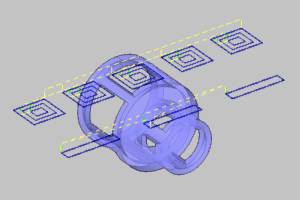
Wrapped Geometry
The Wrapped Geometry check box determines whether the geometry that you assign to features in the wrapping group is drawn unwrapped (flat) or is selected directly from wrapped (cylindrical) geometry. Note that if you change this option after creating features, you must change the geometry selection and compute the feature to update the toolpath for the existing operations to use the new setting.
![]() Select the Wrapped Geometry check box when you want to select wrapped
or cylindrical geometry.
Select the Wrapped Geometry check box when you want to select wrapped
or cylindrical geometry.
![]() Clear the Wrapped Geometry check box when you want to select unwrapped
or flat geometry.
Clear the Wrapped Geometry check box when you want to select unwrapped
or flat geometry.
Show Toolpath as Wrapped
You can display any wrapping toolpath (whether selecting flat or wrapped geometry) as either flat or wrapped. Note that changing the state of this option automatically updates the toolpath display in the graphics area (you do not need to recompute).
![]() Select the Show Toolpath as Wrapped check box when you want to display
the calculated toolpath as wrapped (or cylindrical). This option displays
the toolpath as it is cut on the machine.
Select the Show Toolpath as Wrapped check box when you want to display
the calculated toolpath as wrapped (or cylindrical). This option displays
the toolpath as it is cut on the machine.
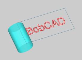
![]() Clear the Show Toolpath as Wrapped check box when you want to display
the calculated toolpath flat.
Clear the Show Toolpath as Wrapped check box when you want to display
the calculated toolpath flat.
Wrapping Diameter
The wrapping diameter can be set in one of two ways. You can manually enter the value, or you allow the software to use the diameter from the stock defined for the job.
-
Wrapping Diameter - type the value of the wrapping diameter used for the features under this wrapping group. The toolpath is calculated using this diameter. Generally, this value is set close to or the same as the stock diameter, but ideally this value is set to the diameter of the selected geometry.
Tip: To achieve the most accurate stepover in wrapping toolpaths, it is recommended that you set the Wrapping Diameter using the diameter at the bottom of the feature (geometry) you are cutting.
-
Use Stock Diameter - automatically sets the Wrapping Diameter value for you based on the currently defined stock geometry.
Important: If you change the Wrapping Diameter after you have already computed a toolpath, you must re-select the geometry for the feature and recompute the toolpath. Re-select in this context means to click Re/Select and just OK the selection (you don't have to actually click the geometry again unless you are changing it).
Unwrap Controls
The unwrap controls are used when you select wrapped (cylindrical) geometry. The software automatically unwraps the geometry in the background before calculating the toolpath. The unwrap controls are used by the software when unwrapping the geometry. These controls are unavailable when the Wrapped Geometry check box is cleared. When selecting geometry that is a significant distance from the wrapping diameter, the tolerance plays a more significant role in the toolpath calculation.
- Unwrap Tolerance - defines
how accurately the software unwraps the selected (wrapped) geometry
before calculating the wrapped toolpath. The default setting of 0.0001
should work well for most parts, but the tolerance can be increased
or decreased as needed. Using a smaller value creates more points
and larger values create less points used when the software unwraps
the geometry in the background.
- Arc Fit - you can select the Arc Fit check box to allow the software to use arcs when unwrapping the geometry in the background. Clear the check box to turn off Arc Fit and the software uses only line segments in the unwrapped geometry.
Wrapping Axis
The wrapping axis parameters are used to define the center of rotation and direction in reference to the machining origin location on the part (machine setup coordinate system). Properly settings these values is required to create a proper wrapping toolpath. Note that the available parameters change slightly depending on the type of job as explained next.
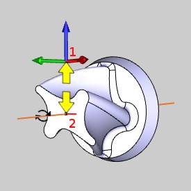
Origin
The X, Y, and Z boxes are used to define the distance from the machine setup coordinate (machining origin) to the wrapping axis origin (or center of rotation) of the part. For example, for wrapping around the X-axis with a four-inch cylinder and the machining origin at the center of rotation, the values are X0Y0Z0. If you were to move the machining origin to the top of the cylinder, meaning that it is moved up along the Z-axis, then you must report the difference. In this case you would enter values of X0Y0Z-2. An example image of the distance is shown next.
Axis Direction (Mill Jobs)
When using wrapping groups in a Mill job, you can select the wrapping axis as follows. For Mill Turn jobs, the wrapping axis is always the Z-axis, so these controls do not display in the dialog box.
-
X Axis - sets the wrapping axis as, or parallel to, the X-axis of the machining origin.
-
Y Axis - sets the wrapping axis as, or parallel to, the Y-axis of the machining origin.
Zero Degree Location
This option is only used when selecting unwrapped geometry for features in the wrapping group. These parameters become unavailable when the Wrapped Geometry check box is selected. The zero degree location is most easily understood if you first think of the machining in a flat plane. The zero-degree location is a distance from the machining origin. This location is aligned with the zero-degree of the wrapped machining. (The zero-degree of a cylinder is the vertical Z-axis or the twelve o'clock position.)
-
Y - sets the distance (along the Y-axis) from the machining origin to the zero degree location of the part (for wrapping around the X-axis or for wrapping in Mill Turn jobs).
-
X - sets the distance (along the X-axis) from the machining origin to the zero degree location of the part (for wrapping around the Y-axis). (This option does not display for Mill Turn jobs.)
View the How to Create a 4 Axis Wrapping Feature example to learn more about the zero degree location.
Important: When creating toolpath patterns using the 3D Rotate option, the toolpath pattern is not applied to any features that are contained in a Wrapping Group.
Geometry Selection Tips for Wrapping Groups
When creating features under a wrapping group, you can select either wrapped or unwrapped geometry. The drawing plane for unwrapped geometry is determined by the job type.
Unwrapped Geometry for Mill Jobs
When selecting unwrapped geometry for Mill jobs, the geometry must be on the XY plane of the machining origin (machine setup) coordinate system defined for the feature.
Unwrapped Geometry for Mill Turn Jobs
When selecting unwrapped geometry for Mill Turn jobs, the geometry must be on the XZ plane of the machining origin (machine setup) coordinate system defined for the feature.
Tip - Wrapping Output is Mirrored
If the output of a wrapped operation is mirrored (or cutting in the wrong direction) on the physical machine's rotary axes, you can resolve the issue by reversing the sign for the appropriate wrapping axis in the post processor, for example from 2 to -2.
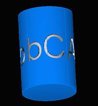
Example
The following image shows the result of the 4-axis wrapping tutorial after backplotting the result. The image shows that the text is cut backwards or mirrored from the expected result.
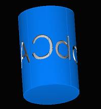
This issue is easily resolved with the following example steps.
-
Open the post processor for the job in any text editor.
-
Go to questions 442-444.
-
Locate the wrapping axis that needs reversed from one of these questions.
For this example, the rotary axis is along the X-axis, as for typical 4-axis machines. -
At the end of question 442, we change the sign from 1 to -1.
-
Save the file to update the post processor.
-
Post the program in Bob
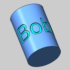
For this example, the change we made reverses the direction of the A-axis rotation angles in the NC program.
After posting the program with the modified post processor and backplotting, the expected result is achieved.