Indexing Programs and Index Systems
Introduction
This topic will explain index systems, explain how to access them, and will describe the options found in the dialog. This topic will also explain the options found in the context menu of the index system item in the Machine Setup, and will provide links to related topics.
Index Systems
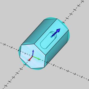
The Index System defines the rotary angles used for 4- or 5-axis indexing. You add an Index System to define each plane of the part that is machined. To define the plane, you can select a surface or a UCS (user coordinate system). Milling Features can then be created for each Index System. When you use Index Systems, the complete program (including the indexing of the part) can be viewed in simulation.
You can also create indexing programs using the Output Rotary Angle option in the Posting dialog box of the Milling Wizard. This method creates proper indexing in the NC program, but the indexing of the part is not shown in simulation.
Important: Wrapping Groups are only available with the 4 Axis Standard, 4 Axis Pro, 5 Axis Standard, and 5 Axis Pro modules.
Navigation
To create an Index System:
- In the CAM Tree, right-click
 Machine Setup, point
to Additional Functions,
and click Add Index.
Machine Setup, point
to Additional Functions,
and click Add Index. - The Index System Selection dialog appears to allow you to specify the location and orientation of the index system.
- Click OK.
The Index System is created and added to the Machine Setup.
After creating the first Index system:
-
Right-click
 Index System, point to Additional Functions, and click
Insert Index.
Index System, point to Additional Functions, and click
Insert Index. - The Index System Selection dialog appears to allow you to specify the location and orientation of the index system.
- Click OK.
The Index System is created and added to the Machine Setup.
Index System Selection Dialog
-
 Pick a Surface - allows you select a surface from the graphics area. The indexing system will then be aligned with surface normal.
 -
 Pick a UCS - with this option selected, the Selected Geometry list box will disappear, and a drop down list of the current UCS planes will be available to select from instead.
Selected Geometry
|
|
|
| The list box will list the entity currently selected for the function. | |
- Reverse - will flip the direction of the index system.
Use Machine Setting for Posting
![]() - will use the posting settings assigned for the machine in the Multiaxis Posting page of the Current Settings.
- will use the posting settings assigned for the machine in the Multiaxis Posting page of the Current Settings.
![]() - will use the posting settings assigned below.
- will use the posting settings assigned below.
Use Transform Plane
![]() - will output Fanuc G68.2 or equivalent.
- will output Fanuc G68.2 or equivalent.
![]() - will not output Fanuc G68.2 or equivalent.
- will not output Fanuc G68.2 or equivalent.
| Machine Setup | Indexing System |
|
|
|
Use Index System Origin
![]() - will output the transform plane, and output coordinates from the location of the indexing system.
- will output the transform plane, and output coordinates from the location of the indexing system.
![]() - will output the transform plane, but output coordinates from its original location.
- will output the transform plane, but output coordinates from its original location.
|
|
|
The Index System Shortcut Menu
Right-click Index System to access a shortcut menu with the following items.
![]() Index System
Index System
- Re/Select - opens
the Index
Important: When you select a surface or plane to set the index location, the surface or plane becomes the Z-axis zero for setting the feature parameters.
- Reverse Direction - is
used to flip the Z-axis indicator of the index system when the
indicator points in the wrong direction. The index system indicator
should point in the positive Z-axis direction (towards the milling
spindle/tool).
- Mill Drill Hole
- opens the Hole Wizard for you to create a Drill Hole feature.
This handles drilling with the available operations: Center Drill,
Drill, Chamfer Drill, Chamfer Mill, Ream, and Bore.
- Mill Tap Hole
- opens the Hole Wizard for you to create a Tap Hole feature.
This handles tapping with the available operations: Center Drill,
Drill, Chamfer Drill, Chamfer Mill, Ream, Bore, Tap and Rolling
Tap.
- Mill Counterbore
Hole - opens the Hole Wizard for you
to create a Counterbore Hole feature. This handles counterbore
hole drilling with the available operations: Center Drill, Drill,
Chamfer Drill, Chamfer Mill, Ream, Counterbore Drill, and Counterbore
Mill.
- Mill Counterbore
Tap Hole - opens the Hole Wizard for
you to create a Counterbore Tap Hole feature. This handles counterbore
hole tapping with the available operations: Center Drill, Drill,
Tap, Rolling Tap Chamfer Drill, Chamfer Mill, Ream, Counterbore
Drill, and Counterbore Mill.
- Mill2
Axis - opens the 2 Axis Wizard for you to create
a 2 Axis feature. This handles 2-axis machining with the available
operations: Profile Rough, Profile Finish, Pocket, Facing, Engraving,
Chamfer Mill, and Plunge Rough.
- Mill 3 Axis -
opens the 3 Axis Wizard for you to create a 3 Axis
feature. This handles 3-axis machining with the available operations:
Z Level Rough, Z Level Finish, Planar, Spiral, Radial, Plunge
Rough, Advanced Rough, Flatlands, Equidistant, and Pencil.
- Mill 4 Axis Rotary
- opens the 4 Axis Rotary Wizard for you to create
a 4 Axis Rotary feature. This handles simultaneous 4-axis rotary
machining with the available operation: 4 Axis Rotary.
- Mill Multiaxis - opens
the Multiaxis
Wizard for you to create a Multiaxis feature. This handles
multiaxis machining up to 5-axis output with the following toolpath
types: Wireframe, Multiaxis Roughing, Swarf and the surface-based
paths Parallel Cuts, Cuts Along Curve, Morph Between 2 Curves,
Parallel to Multiple Curves, Project Curves, Morph Between 2 Surfaces,
and Parallel to Surface.
- Mill Thread - opens
the Mill Thread Wizard for you to create a Mill Thread feature.
This handles mill threading with the available operations: Center
Drill, Drill, Chamfer Drill, Chamfer Mill, Ream, Bore, Pocket,
and Profile.
- Mill 3 Axis Wireframe
- opens the 3 Axis Wizard for you to create a 3 Axis
Wireframe feature. This handles 3D engraving with the available
operations: 3D Engrave Rough and 3D Engrave Finish.
- V-Carve - opens
the V-Carve Wizard for you to create a V-Carve feature.
This handles tapered pocketing and V-tool carving using the available
operations: Tapered Pocket and V-Carve Finish.
- Additional Functions
- point to this menu item to view the following commands.
- Update All Geometries
- updates all the geometry associated with the
feature.
- Compute All
Toolpath - computes the operations of all features
contained in the Index System.
- Insert Index
- adds an Index System to the tree after this index system.
- Insert Wrapping Group
- places a wrapping
group in the CAM Tree.
- Add Toolpath
Pattern - adds a Toolpath
Pattern to the selected Index System. When added from
this location, the defined pattern is applied to all of the
features in the Index System.
- Remove -
removes the assigned indexing plane from the index system.
- Delete -
removes the Index System from the tree.
- Delete All Features
- removes all milling features in the Index System.
- Collapse Items
- collapses the child items of the Index System. This is the
same as clicking the minus sign (
 ) next
to all child items.
) next
to all child items. -
Expand Items - expands the child items of the Index System. This is the same as clicking the plus sign (
 ) next to all child
items.
) next to all child
items.
- Load Feature
- allows you to locate and add a previously saved milling feature
to the tree.
- Paste Feature
- is used to paste a copied feature to the Index System after
the last feature.
- Post All Yes/No
- sets all toolpaths in the Index System to post or not post in
the NC program.
- Blank/Unblank Toolpath
- allows you to hide or show all toolpaths in the Index System.
- Rename - enables editing of the Index System name in the CAM Tree. Type the new name for the index.
Using the Index System
Rotation angles are automatically set in features created using an Index system as long as the proper procedure is followed.
The Proper Setup Procedure:
-
Define the stock geometry and Machine Setup for the part.
-
Add an Index System, and assign the plane for the index system before adding features.
-
When you add features, you must right-click the Index System (not the Machine Setup) to automatically pick up the proper rotation angles.
(If you add a feature from the Machine Setup, the feature isn't added to the Index System.)
Note: When you select a surface/plane to set the index location, the surface/plane becomes the Z-axis zero for setting the feature parameters.