Advanced Options for Surface Quality
Introduction
This topic will explain the Advanced options for surface quality dialog, will explain the options found in it, will describe how to access it, and will provide links to related topics.
Advanced options for surface quality
The Advanced options for surface quality dialog is available for all surface based toolpaths, and deals with the points that are created on a surface which are used to define the toolpath precision. For one cut along a flat surface with no tool tilting, two toolpath points are sufficient. Curved surfaces require many more points to account for constantly changing surfaces and tool tilting. Even though a tolerance is used, the amount of toolpath points needed varies greatly from one surface to the next. For surfaces with less toolpath points (flat or slightly curved) the Chaining Tolerance allows more control over the accuracy of the toolpath.
Navigation
To access the Advanced Options for Surface Quality dialog box:
- In the tree on the left side of the Multiaxis Wizard dialog box, click Parameters.
- In the Surface Paths tab under Surface Quality, click Advanced.
The Dialog Box Parameters
Pattern Creation
- Step over calculation method - allows you to select from the standard surfaced based calculation method or a geodesic calculation method.
Tip: Surfaced based calculations are not ideal for all situations. If you encounter a poor toolpath result, select the Exact option for a geodesic calculation and recompute.
-
Approximate - Surfaced based calculation.
-
Exact - Geodesic calculation.
-
Chaining Tolerance - defines the maximum variation for creating toolpath points.
Tip: The Chaining tolerance is usually between one and one-hundred times the Cut tolerance. The value used greatly affects the toolpath calculation time. See the bottom of the topic for an example.
- Slow and Safe Path Creation
 Select
this check box to have the system use the Maximum Stepover value as
the greatest possible chaining tolerance value. This will increase
toolpath calculation time.
Select
this check box to have the system use the Maximum Stepover value as
the greatest possible chaining tolerance value. This will increase
toolpath calculation time. Clear the check box to turn off this option.
-
Adaptive Cuts
- (this option is not available for all strategies)
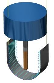
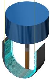
Select the check box to create morphing toolpaths with a consistent stepover. This will increase the toolpath calculation time.
Clear the check box to turn off adaptive cuts and use a normal stepover.
|
|
|
|
|
Note: Notice the difference in the stepover at the bottom.
- Synchronize points - allows you to attempt to equalize the spacing and number of points on all contours. This method is available only when maximum distance is also activated. - The points are only determined by the cut tolerance and max angle change value. - The points are aligned.
|
|
|
|
|
Toolpath smoothing
- Smooth toolpath - This option smooths sharp corners in the toolpath and replace them with splines. - No smoothing will be done on the toolpath. - Smoothing will be applied to the toolpath based on the Smoothing distance and Detection angle used.
|
|
|
|

|
- Smoothing distance - this parameter sets the spline distance.
- Detection angle - this parameter sets a minimum detection angle, which is calculated from the angle between the previous vector move and the next move.
Point Distribution
- Maximum distance -
sets a limit on distance between toolpath points.
- Minimum distance -
eliminates toolpath points that are too close together based on the value
entered.
- Deviation factor - When eliminating
points using the Minimum distance option, the deviation factor will
ensure the alterations in the new toolpath remain within a particular
range. See image below.
Examples
Chaining Tolerance
The following situations are described below usingParallel to Curve: (1) The toolpath forms a cusp between two close segments. (2) The toolpath is interrupted by a gap.
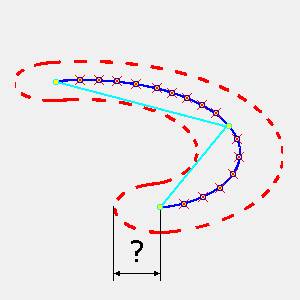
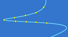
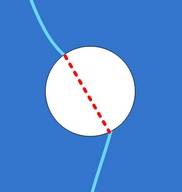
1) The toolpath forms a cusp: In the next image the yellow dots represent possible toolpath points along the toolpath.
-
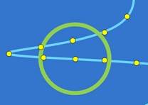
We can consider that the chaining tolerance is as a circle around the present toolpath points. The larger the tolerance-the more points are covered by the circle.
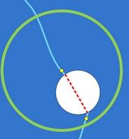
-
The chaining tolerance (the circle) is catching many toolpath points. Because of this, the algorithm uses the wrong points in the chain and the toolpath is generated cutting off some toolpath segments.
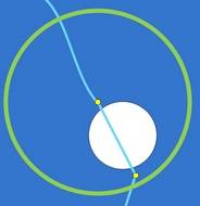
-
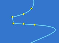
To assure the right chaining, the tolerance must be decreased.
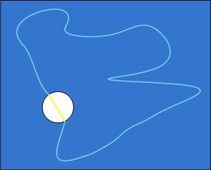
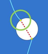
2) The situation when the toolpath is interrupted by a gap. The tool should retract as indicated in Gaps along cut in the Links page.
-
If a large tolerance is used, the gap might not even be recognized.
-
The wrong chaining would avoid the gap totally.
-
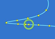
A smaller tolerance would find the gap.
The chaining tolerance can be thought of as a value used to define a search range in finding the next correct toolpath point. The more flat a surface is, the smaller a chaining tolerance must be. It is recommended to select the chaining tolerance between 1 and 100 times larger than the cut tolerance. This should work for most cases. But if the smaller tolerance is selected, more time is needed for computing the toolpath.
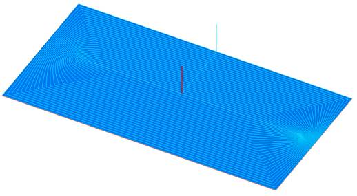
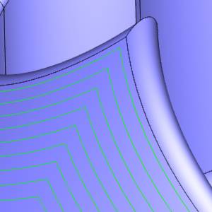
The next image illustrates a flat surface with the toolpath pattern Morph Between 2 Curves. The two curves are the outer boundary of the face and a thin contour inside the face.
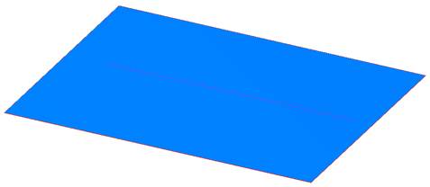
-
The thin contour inside is also a closed contour. This image shows one contour edge.
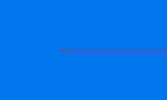
-
With the chaining tolerance set to 2mm the resulting toolpath shows a gap close in the toolpath. The chaining of the toolpath points went wrong.
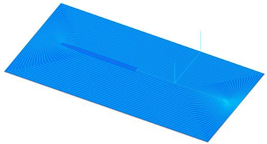
-
The reason for this is the large chaining tolerance. Notice in the previous image that at the inner curve the toolpath on both sides are very close together. What happened here is that the toolpath was connected accidentally to a wrong toolpath point. A smaller chaining tolerance helps.