Drive Surfaces
Introduction
The Drive Surfaces are a selection of one or more surfaces upon which
the toolpath is created. Most important for the selection is the normal
direction of the surfaces/faces. Since a surface has two sides, the toolpath
is determined to be located on the front side of the surface. The front
side is the side where the surface normal shows out. For solids, the normal
direction is usually easily defined, it points outside
of the model. An exception is when a part file is imported or converted
and the surface normal directions change. Changing the surface normal
direction is accomplished using the ![]() Reverse Surface Normal
Reverse Surface Normal
- Drive Surfaces - enables selection mode for you to select geometry upon which the toolpath is generated.
- Drive Surfaces Offset -
creates a 3D offset of the drive surface geometry. This is used to
leave stock remaining on the part.
Reversing the Surface Normal Direction
Tip: To show the surface
normals, in the document toolbar, click ![]() Surface Normal. You can also use the
keyboard shortcut N to toggle the visibility of the surface normal (click
anywhere in the graphics area to give it key focus first).
Surface Normal. You can also use the
keyboard shortcut N to toggle the visibility of the surface normal (click
anywhere in the graphics area to give it key focus first).
How to Reverse the Surface Normal Direction
When preparing to create Multiaxis toolpaths, you must check the surface normal direction of the part to assure that the toolpath is created on the proper side of the surfaces/faces.
-
To show the surface normal direction, in the document toolbar, click
 Surface Normal.
You can also press N to hide or show the surface normal.
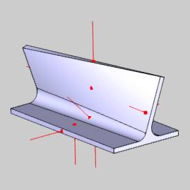
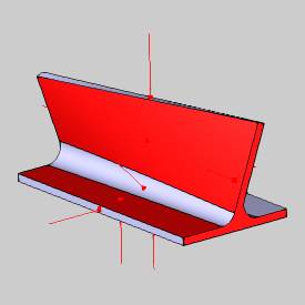
The following image shows a part that has three faces with incorrect normal directions. (These are the floor face, the vertical wall face, and the face on the right-end of the part.)
-
To change the normal direction, use the
 Reverse Surface Normal function found in the Reverse group, of the Utilities ribbon.
 -
In the graphics area, click to select each face/surface that has an incorrect normal direction.

-
To confirm your selections, right-click anywhere in the graphics area, and click
 OK.
OK.
You can also press Spacebar.
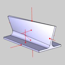
When you confirm the selections, the normal direction is reversed for each selected face.
Notice the new direction of the normal for each of the selected surfaces compared to the original directions. The surface normal must show (point out and away) from the side that is being machined. -
To cancel the function, in the Data Entry tab, click Cancel.
This concludes the example.
