Milling Features Overview
Introduction
This topic will introduce Milling Features, how to create them, and how to work with existing features. This topic will also provide links to related topics.
Milling Features
Milling Features can be thought of as simply as you would the features of the final product itself. For any feature of the part itself, work will have to be done to create it. Any work you choose to do on a feature will be an operation that you add. To create a feature, right-click on the Machine Setup and choose one of the available features. Once the feature is chosen and the Wizard is launched, you will be able to select any number of operations needed to complete the chosen feature.
When the feature is finished, the feature is added to the Mill Job in the CAM Tree. All of the information from the wizard can be viewed or modified using the feature in the CAM Tree. Each item of the feature contains a shortcut menu for you to access various functions and commands.
 Creating
Features
Creating
Features
Introduction
The Milling Wizard contains multiple dialog boxes arranged to lead you through defining your Milling features. This includes selecting feature geometry, defining the feature-level parameters, and then defining the operation-level parameters. When you add a Milling feature in the CAM Tree, the Milling Wizard displays. The setup process, navigation, and all parameters are explained in the Milling Wizard help topics.
Navigation
To create a Milling feature:
- In the CAM
Tree, right-click
 Machine Setup, and select
a milling feature type in the context menu.
Machine Setup, and select
a milling feature type in the context menu.
The Milling Wizard displays.
The Milling Wizard Overview
-
Add a Milling feature based on the target geometry.
-
In the first page of the wizard, you assign the
feature geometry.
Note: After finishing the wizard, any changes to the feature geometry
are made using the CAM Tree. The geometry item in the wizard is
not available when editing a feature.
-
In the second page of the wizard, you define the
feature parameters.
The settings you define here are applied to all operations in the feature. -
In the third page of the wizard, the Machining
Strategy, select a Template for the feature.
Modify the Current Operations to contain the desired number and order of operations for the feature.
Note: When editing a feature, the Template of the Machining Strategy
can't be changed. You can still add, remove, or reorder the Current
Operations, it is only the template that can't be changed. This
is done because the Template is used to set Cutting Conditions. You can update the operations used in the Default Strategy templates in the DMS Defaults Dialog, or create User Defined Templates with the Save to Defined Template option.
-
The next step differs between 2 and 3 Axis features.
-
In a 2 Axis feature, the next step is to set
up tabs, if any are needed for the part. After the Tabs page,
comes the Posting page.
- In a 3 Axis feature, the next step is to modify
the Posting parameters for the feature as needed. Note that
when a multiaxis machine is selected for the job, the Multiaxis
Posting page also displays to handle various posting parameters
for the job.
-
In a 2 Axis feature, the next step is to set
up tabs, if any are needed for the part. After the Tabs page,
comes the Posting page.
-
In the remaining pages of the wizard, you define the operation-level
parameters. This includes the tool data, patterns, parameters,
leads, options, links, advanced feedrates, and MDI for Mill Turn jobs, for each operation that you selected
for the feature.
- If, while moving through the wizard, you notice default values you believe should be updated to fit your needs better, you can select Save Defaults at the bottom of the wizard to save your values to a template. See The Default Parameter Templates topic for more information.
- After defining the feature parameters, compute the toolpath
for the feature and examine the results.
If any changes need made, edit the feature, and compute to add the changes.
Existing
Features
Navigation
To edit a Milling feature:
-
In the CAM Tree under
Machine Setup, right-click
 Feature
Name,
and click Edit.
Feature
Name,
and click Edit.
Note: The Feature Name is the top-level item of the Feature in the CAM Tree.
The Milling Wizard displays.
Introduction
When you create a milling feature and finish the feature in the wizard, the feature is added to the CAM job in the CAM Tree. All of the information from the wizard can be viewed or modified using the feature in the CAM Tree. Each item of the feature contains a context menu for you to access various functions and commands.
Probing Feature
|
Mill Drill Hole Feature
|
Mill 2 Axis Feature
|
Mill 3 Axis Feature
|
Mill 4 Axis Rotary Feature
|
Mill Multiaxis Feature
|
The Feature Context Menus
You right-click each feature item in the tree to access a context menu. The menus handle various software commands as explained next.
Feature Creation and Modification
The top level of the feature, which displays the feature name, is used to edit the feature, add features, and set the feature status using the following commands.
Note: When you insert a feature, it is added below the current feature.
![]() Feature Type >>
Feature Type >>
- Edit - opens
the Milling Wizard for you to modify the feature.
- Update All Geometries
- updates all the geometry associated with the
feature.
- Compute All
Toolpath - computes all operations contained
in the feature.
- Insert Mill
Drill Hole - opens the Hole Wizard for you to
create a Drill Hole feature. This handles drilling with the
available operations: Center Drill, Drill, Chamfer Drill,
Chamfer Mill, Ream, and Bore.
- Insert Mill
Tap Hole - opens the Hole Wizard for you to create
a Tap Hole feature. This handles tapping with the available
operations: Center Drill, Drill, Chamfer Drill, Chamfer Mill,
Ream, Bore, Tap and Rolling Tap.
- Insert Mill
Counterbore Hole - opens the Hole Wizard
for you to create a Counterbore Hole feature. This handles
counterbore hole drilling with the available operations: Center
Drill, Drill, Chamfer Drill, Chamfer Mill, Ream, Counterbore
Drill, and Counterbore Mill.
- Insert Mill
Counterbore Tap Hole - opens the Hole Wizard
for you to create a Counterbore Tap Hole feature. This handles
counterbore hole tapping with the available operations: Center
Drill, Drill, Tap, Rolling Tap Chamfer Drill, Chamfer Mill,
Ream, Counterbore Drill, and Counterbore Mill.
- Insert Mill2 Axis - opens the
2 Axis Wizard for you to create a 2 Axis feature. This handles
2-axis machining with the available operations: Profile Rough,
Profile Finish, Pocket, Facing, Engraving, Chamfer Mill, and
Plunge Rough.
- Insert Mill 3 Axis
- opens the 3 Axis Wizard for you to create a
3 Axis feature. This handles 3-axis machining with the available
operations: Z Level Rough, Z Level Finish, Planar, Spiral,
Radial, Plunge Rough, Advanced Rough, Flatlands, Equidistant,
and Pencil.
- Insert Mill 4 Axis Rotary
- opens the 4 Axis Rotary Wizard for you to create
a 4 Axis Rotary feature. This handles simultaneous 4-axis
rotary machining with the available operation: 4 Axis Rotary.
- Insert Mill Multiaxis
- opens the Multiaxis
Wizard for you to create a Multiaxis feature. This handles
multiaxis machining up to 5-axis output with the following
toolpath types: Wireframe, Multiaxis Roughing, Swarf and the
surface-based paths Parallel Cuts, Cuts Along Curve, Morph
Between 2 Curves, Parallel to Multiple Curves, Project Curves,
Morph Between 2 Surfaces, and Parallel to Surface.
- Insert Mill Thread
- opens the Mill Thread Wizard for you to create a Mill Thread
feature. This handles mill threading with the available operations:
Center Drill, Drill, Chamfer Drill, Chamfer Mill, Ream,
Bore, Pocket, and Profile.
- Insert Mill 3 Axis Wireframe
- opens the 3 Axis Wizard for you to create a
3 Axis Wireframe feature. This handles 3D engraving with the
available operations: 3D Engrave Rough and 3D Engrave Finish.
- Insert V-Carve
- opens the V-Carve Wizard for you to create
a V-Carve feature. This handles tapered pocketing and V-tool
carving using the available operations: Tapered Pocket and
V-Carve Finish.
- Insert Index -
places an index
system in the CAM Tree.
- Insert Wrapping Group
- places a wrapping
group in the CAM Tree.
- Add Toolpath
Pattern - adds a Toolpath
Pattern to the selected feature. When added from this
location, the defined pattern is applied to all of the operations
in the feature.
- Save Feature
- opens the Save As dialog box for you to save the current
feature information to a file.
- Load Feature
- allows you to locate and add a previously saved milling
feature to the tree after this feature.
- Copy
- copies the feature so that you can duplicate it by pasting
it into a Machine Setup, Index System, Wrapping Group or after
another feature.
- Paste -
is used to insert (paste) a copied feature into the job after
this feature.
- Post Yes/No
- sets all operations in the feature to post or not post in
the NC program.
- Blank/Unblank
Toolpath - allows you to hide or show all toolpaths
in the feature.
- Lock/Unlock
Operation - allows you to lock and unlock operations.
Locked operations must be unlocked before they are able to
be computed again.
- Delete -
completely removes the feature from the job.
- Rename - enables editing of the feature name in the CAM Tree. Type the new name for the feature.
Editing the Feature Geometry
The feature geometry item of CAM features is used to modify the geometry selected in the wizard.
![]() Geometry
Geometry
- Re/Select - launches the Feature Geometry Picking dialog for you to modify the current feature geometry selection.
The currently selected geometry displays in the graphics area
using the selection color. After making the selections, click
OK (
 ).
). - Remove - eliminates the geometry assignment for the feature. This does not delete the actual geometry, it just removes the assignment of the geometry to the feature.
Compute or Modify an Operation
Each operation that is contained within a feature contains the following commands for the operation.
![]() Operations
Operations
- Edit - launches the wizard and sets the opening page to the toolpage of the particular operation it was launched from.
- Compute Toolpath
- calculates the toolpath for this operation only.
- Backplot
- launches the Backplot
option in the Data Entry Manager to allow you to visualize
the tool movement of the specified operation.
- Copy
- copies this operation so that you can duplicate it by pasting
it into this or another feature.
- Paste
- inserts a copied operation below this operation in the feature.
- Edit Toolpath
- launches the
Edit Toolpath dialog to allow you to manually control
and edit the toolpath itself.
- Color
- opens the Color dialog box for you to change the color of
the operation toolpath in the graphics area.
- Blank/Unblank
- hides or shows the operation toolpath in the graphics area.
- Post Yes/No
- controls whether or not this operation is included in the
posted NC program.
- Lock/Unlock
Operation - allows you to lock and unlock operations.
Locked operations must be unlocked before they are able to
be computed again.
- Rename - enables editing of the operation name in the CAM Tree. Type the new name for the operation.
Setting Chain Start Points for Operations
While the 2 Axis Feature does have its own "Default Chain Start Point", many operations contain a "Chain Start Point" item to define where the tool starts for the individual operation. The initial start point is determined by the software when the toolpath is calculated. You use the following items to modify the start point for various operations.
Note: When using Modify to set the start point and direction of any chain, the chain geometry must be visible in the graphics area in order for you to change the start point location.
The following feature item is used to modify the chain start point (globally) for all operations in a 2-axis feature.
![]() Default Chain Start Point
Default Chain Start Point
- Modify
- displays the start point indicator on the feature geometry
for you to click a new location to set the start point. After
modifying the start point location, click OK () to confirm the
selection. This defines the default start point for all operations
contained in the feature.
- Reverse Direction - flips the current direction of the chain start point to force cutting in the opposite direction.
![]() Chain Start Point
Chain Start Point
- Modify
- displays the start point indicator on the feature geometry
for you to click a new location to set the start point. After
modifying the start point location, click OK () to confirm the
selection.
- Reverse
Direction - flips the current direction of the chain
start point to force cutting in the opposite direction.
- Use Default - sets the chain start point using the Default Chain Start Point of the feature.
Setting Drill Tip Positions
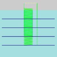
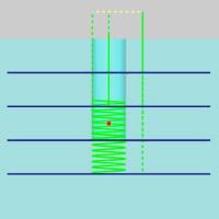
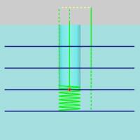
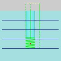
Many operation contain a Drill Tip Position to allow you to define the point at which the tool should move to depth at the beginning of the toolpath.
Important: When using Drill Tip Positions for the Advanced patterns of the 2 Axis Pocket operation, and the 3 Axis Advanced Roughing operation, the selected drill tip point should be at the depth of the pre-drilled hole. Any passes beyond the depth of the point will be handled with the method specified in the Entry group of the Leads page.
| No Drill Tip Position | Drill Tip Position Above Pass 3 | Drill Tip Position On Pass 3 | Drill Tip Position Below Pass 3 |
|
|
|
|
Note: Notice in the images above, the depth is achieved either with a plunge or without. If the point is located above the pass, as it is in the second image, the entire depth is achieved using specified entry method.
Tip: If the operation has various regions, resulting in multiple entry points, multiple Drill Tip Positions can be selected and utilized.
![]() Drill Tip Positions
Drill Tip Positions
- Re/Select - opens the Pick a Point dialog in the Data Entry Manager.
The currently selected geometry displays in the graphics area
using the selection color, and in the Selected Geometry list of the Pick a Point dialog. After making the selections, click
OK ().
- Remove - eliminates the geometry assignment for the feature. This does not delete the actual geometry, it just removes the assignment of the geometry to the feature.
Operation Stock
Certain operations contain Operation Stock. Operation Stock allows you to assign an a solid, or stl model as the stock the toolpath should be trimmed to. While the Advanced Rough will automatically look to the Operation Stock, for the other operations that can use it, select the Trim to Stock option in the Parameters page of an operation in order to utilize the Operation Stock.
![]() Operation Stock
Operation Stock
-
Re/Select - Opens the Operation Geometry Selection dialog for you to select geometry to set as the Operation Stock.
-
Remove - eliminates any selected geometry and returns to default.
Setting Boundaries at the Feature and Operation Level
For 3 Axis features, the boundary selection can be assigned at the feature-level to be applied to all operations in the feature. This is done using the top-most Boundary item contained in a feature (the one displayed below Feature, not an Operation). You can also define a separate boundary for each operation contained in the feature. Use the Boundary item that displays below an operation to apply a boundary to that operation only.
Tip: When you assign a boundary to an operation, the selected boundary overrides the boundary defined at the feature level.
![]() Boundary
Boundary
- Re/Select - opens the Operation Geometry Selection dialog in the Data Entry Manager.
The currently selected geometry displays in the graphics area
using the selection color, and in the corresponding list of the Operation Geometry Selection dialog. After making the selections, click
OK ().
- Remove - eliminates the boundary association with the feature or operation.
Multiaxis Geometry Selections
The Multiaxis features contain many geometry items in the tree that change based on the strategy selected in the wizard. The items and shortcut menus for these features are listed next.
![]() Drive Surfaces
Drive Surfaces
- Re/Select - opens the Feature Geometry Picking dialog in the Data Entry Manager.
The currently selected geometry displays in the graphics area
using the selection color, and in the Selected Geometry list of the Feature Geometry Picking dialog. After making the selections, click
OK ().
- Remove - eliminates the geometry assignment for the feature. This does not delete the actual geometry, it just removes the assignment of the geometry to the feature.
![]() 2D Containment
2D Containment
- Re/Select - opens the Feature Geometry Picking dialog in the Data Entry Manager.
The currently selected geometry displays in the graphics area
using the selection color, and in the Selected Geometry list of the Feature Geometry Picking dialog. After making the selections, click
OK ().
- Remove - eliminates the boundary association with the feature.
![]() Drive Curve/Lead Curve/Edge Curve
Drive Curve/Lead Curve/Edge Curve
- Re/Select - opens the Feature Geometry Picking dialog in the Data Entry Manager.
The currently selected geometry displays in the graphics area
using the selection color, and in the Selected Geometry list of the Feature Geometry Picking dialog. After making the selections, click
OK ().
- Remove - eliminates the
geometry assignment for the feature. This does not delete
the actual geometry, it just removes the assignment of the
geometry to the feature.
- Modify
- opens the Feature Geometry Picking dialog in the Data Entry Manager.
The currently selected geometry displays in the graphics area
using the selection color, and in the Modify Start Point list of the Feature Geometry Picking dialog. After making the selections, click
OK ().
- Reverse Direction - flips the current direction of the chain start point so that it follows the opposite direction.
![]() Gouge Check Surfaces
Gouge Check Surfaces
- Re/Select - enables selection
mode for you to modify or assign the surfaces to be included
in the gouge check. The currently selected geometry displays
in the graphics area using the selection color. After making
the selections, click OK ().
- Remove - eliminates the geometry assignment for the gouge check. This does not delete the actual geometry, it just removes the assignment of the geometry to the feature.
![]() Axis Control
Axis Control
The following options are used to modify geometry selections that are used with the Tool Axis Control section of the Multiaxis Wizard.
- Re/Select - opens the Feature Geometry Picking dialog in the Data Entry Manager.
The currently selected geometry displays in the graphics area
using the selection color, and in the Selected Geometry list of the Feature Geometry Picking dialog. After making the selections, click
OK ().
- Remove - eliminates the
geometry assignment for the feature. This does not delete
the actual geometry, it just removes the assignment of the
geometry to the feature.
- Modify
- opens the Feature Geometry Picking dialog in the Data Entry Manager.
The currently selected geometry displays in the graphics area
using the selection color, and in the Modify Start Point list of the Feature Geometry Picking dialog. After making the selections, click
OK ().
- Reverse Direction - flips the current direction of the chain start point so that it follows the opposite direction.
Tip: You can click some of the CAM Tree items to view a preview in the graphics area. For example, click Geometry to confirm the assigned feature geometry, or click an Operation to confirm a computed toolpath.
Related Topics
The Mill Hole Features Overview
The Mill 2 Axis Feature Overview
The Mill 3 Axis Feature Overview
The Mill 4 Axis Rotary Feature Overview
The Mill Thread Feature Overview
To learn more about the flyouts ( >>) seen in the job, see the CAM Flyouts topic.