Measure
Introduction
This topic explains the Measure tab, and the items found in it. This topic will also provide links to related topics.
The Measure Tab
Measure provides different features to measure out the stock:
-
Points
- Distances
- Refine Box
- Remove chips (select chips)
- Remove chips (only keep 1 part)
- Remove chips (auto, define targets)
- Remove chips (with test)
- Remove chips (auto, based on volume)
Points
Points gives information about the current coordinates X, Y and Z, the tool being used, block number and the deviation.
Example
Move the pointer onto the stock. Then click with the middle mouse button. A point is shown in a small text box in the simulation window. The point is added to the point list.
The information in the text box:
- Point Info -
lists the type of units used.
- Position (WCS)
- indicates the X/Y/Z position based on the machine zero.
- Deviation - when
a deviation report has been run, this will show the distance between
the stock and the workpiece.
- Tool number - when used on material
that has been exposed by a tool, this will show the tool number that
was used to remove the material.
- Block number -
when used on material that has been exposed by a tool, this will show
the block number of the operation that removed the material.
- Target ID - lists the Target ID.
Points List
The Points list will show all the points that have been measured in the current simulation. The data in this list is limited to the X,Y,Z coordinates, along with the Deviation. To clear points, right click in the list and choose between Remove selected items, or Remove all items.
Distances
Distance measures the 3D distance between two points on the stock model or machine component, along with the distance and angle between the X,Y,Z point and the WCS, or machine zero.
Example
Move the cursor onto the stock. Then click the middle mouse button to select the start point and click the middle mouse button again to select an end point. A distance value is shown in a small text box in the simulation window. The item is also added to the distance list. The information in the text box is the 3D distance between the 2 selected points, along with the distance and angle between the X,Y,Z point and the WCS, or machine zero.
The information in the text box:
-
Distance 3D : - lists the direct distance between the selected points.
-
Angle 0X / 0Y / 0Z : - shows the angle relation of the line created by the two separate points for X,Y, and Z axes.
-
Distance dX / dY / dZ : - shows individual X,Y, and Z distances between the two selected points.
Distances List
The Distances list will show all the Distance measurements taken in the current simulation. All measurements will be listed in the No. column. For each measurement, the X,Y,Z coordinates, in relation to the machine zero will be listed as First Point(MCS), and Second Point(MCS). The Angle 0X / 0Y / 0Z data, will be listed as Angle O*, and the Distance dX / dY / dZ data will be listed next to Distance d* To clear Distance measurements in the list, right click in the list and choose between Remove selected items, or Remove all items.
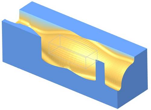
Refine Box
Use the Refine Box to zoom into a certain area of the stock model. The material around the Refine Box is removed, thus using the full resolution for the zoomed area.
Available Controls
![]() (Apply Refine)
- will attempt to improve the resolution of the current view. When a Refine
Box has been defined, this control will remove the material outside of
the Refine Box and attempt to improve the resolution of the area that
box has defined.
(Apply Refine)
- will attempt to improve the resolution of the current view. When a Refine
Box has been defined, this control will remove the material outside of
the Refine Box and attempt to improve the resolution of the area that
box has defined.
![]() (Reset Refine)
- will reset the material to its original state.
(Reset Refine)
- will reset the material to its original state.
Example
Move the cursor onto the stock. Then click the middle mouse button to select the start point, end point, and a point for depth. Use additional clicks of the middle mouse button to further refine the size of the box.
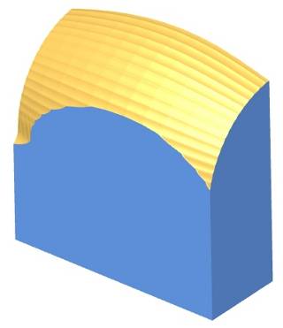
Once the box is the desired size, click ![]() (Apply
Refine) to apply. This process can be repeated again on the refined
area.
(Apply
Refine) to apply. This process can be repeated again on the refined
area.
Click ![]() (Reset
Refine) to get to the original state.
(Reset
Refine) to get to the original state.
Remove chips (select chips)
With this function you can remove pieces of material that have been separated from the stock by cutting.
Available Controls
 (Stop
on new chip detection) - with this toggle active, a STOP Notification
will appear when a chip is created to allow you to decide whether to continue
and whether or not to show the STOP Notification again when particular
situations are encountered.
(Stop
on new chip detection) - with this toggle active, a STOP Notification
will appear when a chip is created to allow you to decide whether to continue
and whether or not to show the STOP Notification again when particular
situations are encountered.
Example
With the simulation completed, or paused, click the middle mouse button on a piece of material and all other material will be removed.
Remove chips (only keep 1 part)
With this function, when a piece of material is clicked on with the center mouse button, all other pieces of material will be removed.
Available Controls
(Stop
on new chip detection) - with this toggle active, a STOP Notification
will appear when a chip is created to allow you to decide whether to continue
and whether or not to show the STOP Notification again when particular
situations are encountered.
Example
With the simulation completed, or paused, click the middle mouse button on a piece of material. The piece of material will be removed from view.
Remove chips (auto, define targets)
With this function, when a piece of material is clicked on with the center mouse button, all other pieces of material will be removed.
Available Controls
(Stop
on new chip detection) - with this toggle active, a STOP Notification
will appear when a chip is created to allow you to decide whether to continue
and whether or not to show the STOP Notification again when particular
situations are encountered.
Example
With the simulation completed, or paused, click the middle mouse button on a piece of material and all other material will be removed.
Remove chips (with test)
With this function, as separate pieces of material are detected, they are color coded, numbered and added to the part list. Parts in the list can be selected by clicking in corresponding check box. Once a part has been selected, the area below the list will show a Setting and a Value group.
Available Controls
![]() - If a part has been tested without being removed, clicking Refresh will
clear the selection and place it back.
- If a part has been tested without being removed, clicking Refresh will
clear the selection and place it back.
 (Test)
- moves the selected part according to the direction selected for testing
and the offset angles used.
(Test)
- moves the selected part according to the direction selected for testing
and the offset angles used.
 (Remove
selected part)-
deletes the selected part.
(Remove
selected part)-
deletes the selected part.
(Stop
on new chip detection) - with this toggle active, a STOP Notification
will appear when a chip is created to allow you to decide whether to continue
and whether or not to show the STOP Notification again when particular
situations are encountered.
The Setting group, will have options:
Selected
part can be separated if moved in direction - will list the axes
the selected part can be moved in to be moved to be removed from the stock.
Selected
direction for testing - allows you to select a direction to test
removal from the stock.
Offset angles:
From direction
axis - allows you to set an angle amount to adjust the direction.
Around direction axis - allows you to set an angle amount to adjust the direction.
Example
With the simulation completed, or paused, click on a parts check box
to select it. The simulation will test various possible removals of the
part and the Selected par can be separated
if moved in direction will list possible axes to use for removal
of the part. Select direction for testing
will allow you to select a particular axis to test removal in the value
section. If necessary, you can enter angle values in the Value
section of the From direction axis,
and Around direction axis items.
When you are ready, click
and removal of the part will be simulated using the direction and offset
angles used. If the part is not removed, you can click ![]() to deselect the part and set it as it was, or simply clear the check box.
To remove the part, click .
to deselect the part and set it as it was, or simply clear the check box.
To remove the part, click .
Remove chips (auto, based on volume)
With this function, you are able to specify the size a chip should be in order to be removed. This can be set to be removed automatically, or can be done once the simulation is complete. .
Available Controls
![]() /
/ ![]() (Refresh) - will update the stock
to delete the chips.
(Refresh) - will update the stock
to delete the chips.
Remove chips
![]() Remove all small chips, keep the largest one -
the largest portion of material will be kept. Any material that has been
separated from the main body will be deleted.
Remove all small chips, keep the largest one -
the largest portion of material will be kept. Any material that has been
separated from the main body will be deleted.
![]() Remove only chips with volume smaller than -
allows you to enter a value representing volume.
Remove only chips with volume smaller than -
allows you to enter a value representing volume.
![]() Automatically remove all small chips and keep the largest one -
With this check box cleared, you will need to click Refresh to update
the stock after the simulation is completed.
Automatically remove all small chips and keep the largest one -
With this check box cleared, you will need to click Refresh to update
the stock after the simulation is completed.
![]() Automatically remove all small chips and keep the largest one -
With this check box selected, the stock will update as the simulation
progresses.
Automatically remove all small chips and keep the largest one -
With this check box selected, the stock will update as the simulation
progresses.
Example
Choose between Remove all small chips, keep the largest one, or Remove only chips with volume smaller than. Play the simulation. With the simulation competed or paused, click Refresh. The chips are removed based on your selection. If the Automatically remove all small chips and keep the largest one check box is selected, the chip removal will occur as the simulation progresses.
Off
This option deactivates the measure function.