The Simulation Tab
Introduction
This topic will explain the Simulation Tab, and the options found in it. This topic will also provide links to related topics.
The Simulation Tab
The Simulation tab contains many of the most used buttons for controlling the simulation. This tab contains the Simulation, Control, Simulation Run Speed, Views, Visibility, and Toolpath Rendering groups. The available buttons for each group are explained next. When hovering over some of these options, you will notice a letter in parentheses. This letter is the available shortcut key to access this item without needing to click on it directly.
Simulation
Backplot or Material Removal Mode
The simulation can be run in one of two modes for material removal or toolpath backplot only.
![]() Toolpath Backplot Mode(B)
- simulates the toolpath only without material removal (the stock
button becomes unavailable as well as many of the material removal verification
tools).
Toolpath Backplot Mode(B)
- simulates the toolpath only without material removal (the stock
button becomes unavailable as well as many of the material removal verification
tools).
![]() Material Removal Mode(V)
- simulates the toolpath including material removal. Many of the features
of the simulation are designed to work with this mode to verify the material
removal.
Material Removal Mode(V)
- simulates the toolpath including material removal. Many of the features
of the simulation are designed to work with this mode to verify the material
removal.
Display Mode
The simulation display mode is controlled using one of the following options.
![]() Time-based Mode - the machining
simulation displays with real time feedrate motions. Machine motions are
very fluent, machining time is exact.
Time-based Mode - the machining
simulation displays with real time feedrate motions. Machine motions are
very fluent, machining time is exact.
![]() NC-based Mode - the machining
simulation only uses the tool positions from the move list. Machine motions
jump from one position to the next.
NC-based Mode - the machining
simulation only uses the tool positions from the move list. Machine motions
jump from one position to the next.
![]() Length-based Mode - the machining
simulation uses a constant speed, distance/time regardless of the feed
rate.
Length-based Mode - the machining
simulation uses a constant speed, distance/time regardless of the feed
rate.
Display Focus
The simulation focus determines how the tool, machine, and material/workpiece display using one of the following options.
![]() Tool Focus(T)
- simulates the program with the tool and workpiece visible, with
the tool remaining stationary.
Tool Focus(T)
- simulates the program with the tool and workpiece visible, with
the tool remaining stationary.
![]() Workpiece Focus (W) - simulates
the program with the tool and workpiece visible, with the workpiece remaining
stationary.
Workpiece Focus (W) - simulates
the program with the tool and workpiece visible, with the workpiece remaining
stationary.
![]() Machine Focus(M)
- simulates the program showing the kinematic motion of all machine
elements.
Machine Focus(M)
- simulates the program showing the kinematic motion of all machine
elements.
Control
The Control group on the Simulation tab contains buttons for controlling the playback of the simulation.
![]() Run (R) - plays the simulation.
You can click the down arrow under this button to select the Loop playback
button. Clicking the down arrow next to the function will show the Loop, and Feed Move Run options.
Run (R) - plays the simulation.
You can click the down arrow under this button to select the Loop playback
button. Clicking the down arrow next to the function will show the Loop, and Feed Move Run options.
![]() Loop (L) - sets the simulation
to run repeatedly, or loops back to the beginning of the simulation when
the end is reached. Clicking the down arrow next to the function will show the Run, and Feed Move Run options.
Loop (L) - sets the simulation
to run repeatedly, or loops back to the beginning of the simulation when
the end is reached. Clicking the down arrow next to the function will show the Run, and Feed Move Run options.
![]() Feed Move Run - does a fast forward movement until the first FEED move, and then returns to normal speed until the next RAPID move is encountered. Another fast forward movement is used until the next FEED move is encountered, and then returns to normal speed. Clicking the down arrow next to the function will show the Loop, and Run options.
Feed Move Run - does a fast forward movement until the first FEED move, and then returns to normal speed until the next RAPID move is encountered. Another fast forward movement is used until the next FEED move is encountered, and then returns to normal speed. Clicking the down arrow next to the function will show the Loop, and Run options.
![]() Stop (S) - stops the simulation
at the current position and retracts the tool for you to view the cut
stock material.
Stop (S) - stops the simulation
at the current position and retracts the tool for you to view the cut
stock material.
![]() Pause (P) - stops
the simulation at the current position without retracting the tool.
Pause (P) - stops
the simulation at the current position without retracting the tool.
![]() FastForward
(Space) - advances the simulation to the last step without showing
the simulation process in the simulation window. If a collision happens
during fast run, it is reported.
FastForward
(Space) - advances the simulation to the last step without showing
the simulation process in the simulation window. If a collision happens
during fast run, it is reported.
![]() Step Fwd (Page Down) - allows
you to incrementally move through the simulation by moving the simulation
to the next toolpath point/segment. Clicking the down arrow next to the function will show the Next Feed Move option.
Step Fwd (Page Down) - allows
you to incrementally move through the simulation by moving the simulation
to the next toolpath point/segment. Clicking the down arrow next to the function will show the Next Feed Move option.
![]() Next Feed Move - jumps over the RAPID moves until the first FEED move is encountered. This is done as a "search" jump, where many functions, like collision checking, are deactivated. This is not a Fast Forward movement. Clicking the down arrow next to the function will show the Step Fwd option.
Next Feed Move - jumps over the RAPID moves until the first FEED move is encountered. This is done as a "search" jump, where many functions, like collision checking, are deactivated. This is not a Fast Forward movement. Clicking the down arrow next to the function will show the Step Fwd option.
![]() StepBack
(Page Up) - allows you to incrementally move through the simulation
by moving the simulation to the next toolpath point/segment. Clicking the down arrow next to the function will show the Prev Feed Move option.
StepBack
(Page Up) - allows you to incrementally move through the simulation
by moving the simulation to the next toolpath point/segment. Clicking the down arrow next to the function will show the Prev Feed Move option.
![]() Prev Feed Move - jumps back over the RAPID moves until the first FEED move is encountered. This is done as a "search" jump, where many functions, like collision checking, are deactivated. This is not a Rewind movement. Clicking the down arrow next to the function will show the Step Back option.
Prev Feed Move - jumps back over the RAPID moves until the first FEED move is encountered. This is done as a "search" jump, where many functions, like collision checking, are deactivated. This is not a Rewind movement. Clicking the down arrow next to the function will show the Step Back option.
![]() Next Op (Enter) -
advances the simulation to the next operation (automatically simulating
the previous operation).
Next Op (Enter) -
advances the simulation to the next operation (automatically simulating
the previous operation).
![]() Previous Op (Backspace)
- returns the simulation to the previous operation.
Previous Op (Backspace)
- returns the simulation to the previous operation.
![]() Restart (Home) - starts machining
over again from the beginning and resets the material removal (Material
Removal mode).
Restart (Home) - starts machining
over again from the beginning and resets the material removal (Material
Removal mode).
Simulation Run Speed
The speed slider allows you to control the speed of playback in simulation.
![]() Simulation Speed (-/=) - allows
you to run the simulation faster or slower. To decrease the simulation
speed move the slider to the left. To increase the simulation speed, move
the slider to the right.
Simulation Speed (-/=) - allows
you to run the simulation faster or slower. To decrease the simulation
speed move the slider to the left. To increase the simulation speed, move
the slider to the right.
Views
The view presets allow you to change the viewing orientation of the elements in the simulation window.
![]() Fit (F) - makes all elements on
the screen fit to the available window size.
Fit (F) - makes all elements on
the screen fit to the available window size.
![]() Isometric (Ctrl - 7) - sets the
isometric view.
Isometric (Ctrl - 7) - sets the
isometric view.
![]() Top (Ctrl - 5) - sets the top
view.
Top (Ctrl - 5) - sets the top
view.
![]() Front (Ctrl - 1) - sets the front
view.
Front (Ctrl - 1) - sets the front
view.
![]() Right (Ctrl - 4) - sets the right
view.
Right (Ctrl - 4) - sets the right
view.
![]() Bottom (Ctrl - 6) - sets the bottom
view.
Bottom (Ctrl - 6) - sets the bottom
view.
![]() Left (Ctrl - 3) - sets the left
view.
Left (Ctrl - 3) - sets the left
view.
![]() Back (Ctrl - 2) - sets the back
view.
Back (Ctrl - 2) - sets the back
view.
Visibility
The visibility group of the Simulation tab provides options for you to change the visibility status of various items in the simulation window. Most of these buttons have four states: show, opaque, transparent, or hide. Each time you click the main button, it changes to the next option. You can also click the down arrow that displays under the button to select the exact status you want from a list. While most of these options are self explanatory, the opaque option actually sets the tool to the transparency level set in the Machine Definition of the Current Settings.
![]() Toolpath - toggles whether or not the toolpath is visible.
Toolpath - toggles whether or not the toolpath is visible.
![]() Tool - provides the options for the visibility of the tool in use.
Tool - provides the options for the visibility of the tool in use.
![]() Fixture - provides the options for the visibility of the fixture in use.
Fixture - provides the options for the visibility of the fixture in use.
![]() Workpiece - provides the options for the visibility of the selected workpiece.
Workpiece - provides the options for the visibility of the selected workpiece.
![]() Stock - provides the options for the visibility of the designated stock.
Stock - provides the options for the visibility of the designated stock.
![]() Initial Stock -
provides the options for the visibility of the stock in its original state.
Initial Stock -
provides the options for the visibility of the stock in its original state.
![]() Machine Housing - provides the options for the visibility of the machine housing.
Machine Housing - provides the options for the visibility of the machine housing.
Toolpath Rendering
The Toolpath Rendering group provides control over how the toolpath displays in the simulation window. Note that all of these options become unavailable when the toolpath visibility is set to hide.
![]() Tool Center - the toolpath displays
at the tool center.
Tool Center - the toolpath displays
at the tool center.
![]() Tool Tip - the toolpath displays
at the tool tip position.
Tool Tip - the toolpath displays
at the tool tip position.
![]() All Operations - shows the toolpath
for all operations.
All Operations - shows the toolpath
for all operations.
![]() Current Operation - shows the
toolpath for the current operation only.
Current Operation - shows the
toolpath for the current operation only.
![]() Thicken Operation - represents the
toolpath for the current operation with more pixels than the other operations.
Thicken Operation - represents the
toolpath for the current operation with more pixels than the other operations.
![]() Follow - shows only the machined
toolpath.
Follow - shows only the machined
toolpath.
![]() Trace - shows only the remaining
toolpath.
Trace - shows only the remaining
toolpath.
![]() Segment - highlights the current
toolpath segment during each tool movement.
Segment - highlights the current
toolpath segment during each tool movement.
![]() Tool Vector - shows the tool-axis
vectors at each toolpath point.
Tool Vector - shows the tool-axis
vectors at each toolpath point.
![]() Toolpath Points - indicates each
toolpath segment with start and end points.
Toolpath Points - indicates each
toolpath segment with start and end points.
![]() Layer Interval - turns on the layer interval view. Clicking the down arrow gives you access to:
Layer Interval - turns on the layer interval view. Clicking the down arrow gives you access to:
![]() Layer Interval Settings - is technically designed to work with simulations of 3D Printing, which BobCAD-CAM does not support. However, this can be utilized to show only the toolpath which is within a specified height range.
Layer Interval Settings - is technically designed to work with simulations of 3D Printing, which BobCAD-CAM does not support. However, this can be utilized to show only the toolpath which is within a specified height range.
Layer Thickness - allows you to enter the measurement increment to adjust the height by in the Manual text field.
![]() Automatic - is not available in BobCAD-CAM.
Automatic - is not available in BobCAD-CAM.
![]() Manual - allows you to set the increment used to set the height range.
Manual - allows you to set the increment used to set the height range.
Sectioning by Layer - this group will allow you to show a specific height range, in the increment specified in the Layer Thickness group.
![]() Show Single Layer (based on Layer Thickness) - shows a set height range specified in the Layer Thickness section. Where the set height range is located can be adjusted with the steppers, or the slider.
Show Single Layer (based on Layer Thickness) - shows a set height range specified in the Layer Thickness section. Where the set height range is located can be adjusted with the steppers, or the slider.
![]() Show Layer Range - allows you to specify a specific range, and gives you independent control over the location of the upper, and lower-most layers shown. This will also allow you to set the colors of the section planes, and give you control over whether they are shown.
Show Layer Range - allows you to specify a specific range, and gives you independent control over the location of the upper, and lower-most layers shown. This will also allow you to set the colors of the section planes, and give you control over whether they are shown.
![]() Upper Layer - activates the Upper Layer and gives you control of its location using the steppers, or the slider.
Upper Layer - activates the Upper Layer and gives you control of its location using the steppers, or the slider.
![]() Upper Layer - turns off the Upper Layer.
Upper Layer - turns off the Upper Layer.
![]() Show Section Plane - shows the Upper Layer, and displays the color the Upper Layer is shown in.
Show Section Plane - shows the Upper Layer, and displays the color the Upper Layer is shown in.
![]() Show Section Plane - hides the Upper Layer from view.
Show Section Plane - hides the Upper Layer from view.
![]() Lower Layer - activates the Lower Layer and gives you control of its location using the steppers, or the slider.
Lower Layer - activates the Lower Layer and gives you control of its location using the steppers, or the slider.
![]() Lower Layer - turns off the Lower Layer.
Lower Layer - turns off the Lower Layer.
![]() Show Section Plane - shows the Lower Layer, and displays the color the Upper Layer is shown in.
Show Section Plane - shows the Lower Layer, and displays the color the Upper Layer is shown in.
![]() Show Section Plane - hides the Lower Layer from view.
Show Section Plane - hides the Lower Layer from view.
Note: The total range shown is always relative to the highest and lowest toolpath points. The max and min range will always be .25 above the highest point, and .25 below the lowest point. If, when in inch mode, .25 is used for the Layer Thickness, the Sectioning by Layer group will be counting .25 increments. So, with that in mind, if the upper layer is set to 11, we will multiply that by our Layer Thickness of .25 to see where our Upper Layer is in relation to the lowest toolpath point.
![]() Leads - shows or hides the lead-in
and lead-out of the toolpath.
Leads - shows or hides the lead-in
and lead-out of the toolpath.
![]() Links - shows or hides the linking
portions of the toolpath.
Links - shows or hides the linking
portions of the toolpath.
![]() Current Layer - is designed to work with systems that support simulation of 3D Printing, and is not applicable in BobCAD-CAM.
Current Layer - is designed to work with systems that support simulation of 3D Printing, and is not applicable in BobCAD-CAM.
Rotation Cube
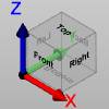
The Smart View feature can be used by a simple click on each of the faces of the cube which is available in the graphical area. On the cube faces there are written the names of the views Top, Bottom, Right, Left, Front, and Back.
Other Controls in the Simulation Window
The viewing orientation of the elements in the simulation window can be controlled using the mouse as follows.
To pan the view, or shift the objects in the simulation window two-dimensionally, press and hold the right mouse button while dragging around the screen.
To zoom in or out, or move the objects in the simulation window closer or further away, roll the middle mouse button forward or backward.
To rotate the viewing orientation of objects in the simulation window, click and drag the left mouse button. Note that rotation occurs around the location that you click.
To access the right-click menu, double right-click in the simulation window. If you double right-click on an object, the object will highlight and you will see options to show, view as opaque, make transparent, or hide. If you right-click on a tool there will also be other options to control the view of the holder, arbor, shaft and flute individually.
- Zoom Window - will allow you to click once to set the first corner of the zoom window, adjust the mouse location to set the opposite corner of the zoom window, and click again to zoom into the created window.
- Pick-Point Dynamic Rotation
- allows you to click a point on the model or machine to set as the
point of rotation. Left-click once to disable.
- Other Visibilities - gives you access to the Show, Opaque, Transparent, and Hide views for the following items.
- Toolpath
- Tool
- Fixture (is not currently supported)
- Workpiece
- Stock
- Initial Stock
- Machine Housing
Note: With the Show visibility in use, the simulation will use the transparency settings that have been assigned in the Machine Definition of the Current Settings dialog. Opaque will show the item as a solid regardless of any transparency settings applied in the machine definition.
- Fit to Screen - Fits all items
into the simulation window.
- Isometric - Shifts items
into an isometric view.
- Other Views - Accesses
the Top, Bottom, Front, Back, Right and Left views.
- Fullscreen Mode - will hide the ribbon, and any open tabs to maximize the size of the simulation viewport. Selecting this again will return the ribbon and tabs to their previous settings.
- Viewports - allows you to select a viewport option which can divide the simulation viewport into multiple views. See the View Tab topic for more information.
- Previous View - allows you to select from previous zooms and orientations used in the current instance of the simulation.
- Capture Graphics Area -
Saves a screen shot of the simulation to the folder specified in Capture
Options.
- Start Capture Video - Beings
recording the simulation window. Recording mode is evident by a red
dot in the top right corner of the simulation window. To stop the
recording, double right-click again and select Stop Capture Video.
- Capture Options... - launches the Machine Simulator Options.
Related Topics
Getting Started With Simulation