Assigning Lathe Tool Inserts
Introduction
BobCAM allows you to assign geometry to define custom lathe tool inserts for tools that can't be created using the provided insert types.
To Assign a Tool Insert
-
In the graphics area, draw the 2D shape of the insert.
At the position of the attachment point to
the tool holder, place a
Place a point at the theoretical tool point.
This point is normally tangent to the forward
and bottom extents of the tool nose radius.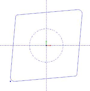
-
To open the Tool Library, do one of the following:
-
Right-click
 CAM Defaults,
and click Tool Library:
CAM Defaults,
and click Tool Library: - Right-click
 Turning
Tools, and click Tools.
Turning
Tools, and click Tools.
-
In the Tool Library, select the lathe tool category that you want to modify.
-
In the list on the right side of the dialog box, click the tool that you want to modify, and click Modify.
(If you are creating a new tool, just select the category, and click Add.)
-
In the Create/Modify dialog box, select the radio button for Custom Shape.
-
Click Assign Tool Insert.
Note: The Tool Attachment Circle is only required if the insert is to be associated with a tool holder.
-
In the Workspace, to select the insert geometry, click and drag a window around the entire drawing.
-
Right-click anywhere in the graphics area, and in the shortcut menu, click
 OK.
OK.
The holder geometry is now assigned to the selected tool.
Click OK to save the changes and return to the Tool Library.